In a previous tutorial VHDL Tutorial 3, we learned how to design, simulate and verify any digital circuit in VHDL using Altera's VHDL MAX+II simulator software.
(If you are not following this series of VHDL tutorials one by one, you will be asked to go through all the previous tutorials in this series before proceeding in this tutorial)
In this tutorial,
- We will write a VHDL program to build all digital ports
- Simulate the program to design digital circuit for all ports
- Check the program output waveform (digital circuit) with the truth table of these logic GATES
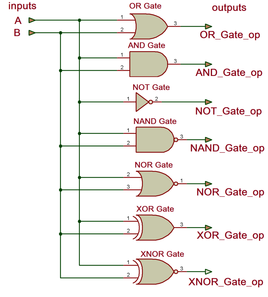
Let's start with the digital circuit for which we will write a VHDL program
Digital Circuit
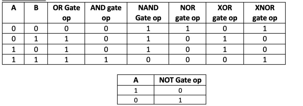
 Here is the truth table for the above circuit.
Truth table
 Now let's write a VHDL program, compile it, simulate it and get the output in the form of a waveform. Finally, we will check these output waveforms with the given truth table.
(Please follow the step-by-step procedure provided in the previous tutorial (VHDL Tutorial 2) to create a project, edit and compile a program, create a waveform file, simulate the program, and generate output waveforms.)
VHDL Program
IEEE library;
use IEEE.STD_LOGIC_1164.ALL;
logic_gate entity is
Port (A,B: in std_logic;
y_and,y_or,y_nand,y_nor,y_not,y_xor,y_xnor : outside std_logic);
end logic_gate;
all_gates architecture of logic_gate is
to start
y_and <= a and b;
y_ou <= a or b;
y_nand <= a nand b;
y_nor <= a nor b;
y_not <= is not one;
y_xor <= a xor b;
y_xnor <= a xnor b;
terminate all_gates;
“ entity ” describes the input-output connections of the digital circuit. As per our circuit given above, we have only two inputs 'A' and 'B' and 7 outputs for 7 ports.
“ Architecture ” describes the operation of the circuit – it means how the output is generated from a given input.
(To learn more and get more details about the VHDL program(s), read the first two tutorials VHDL Tutorial 1 and VHDL Tutorial 2 in this series.)
Next, compile the above program – create a waveform file with all inputs and outputs listed – simulate the project and you will get the following result:
Simulation Waveform
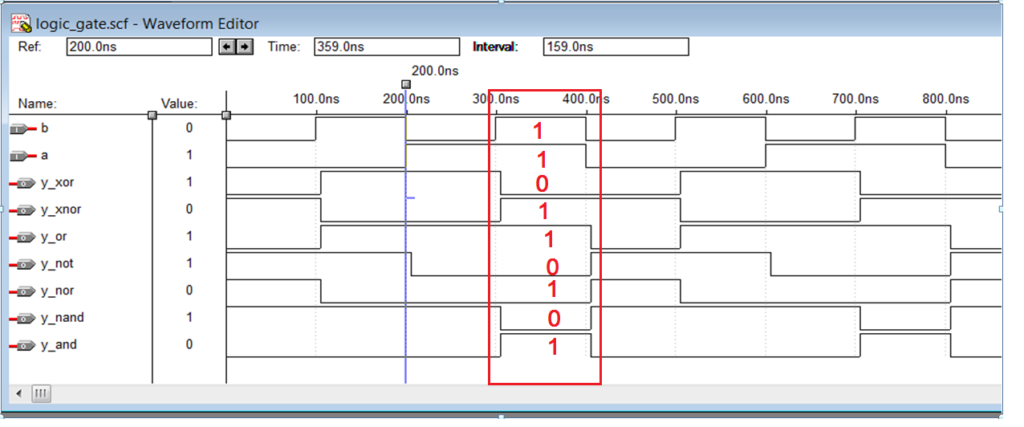 Now check these output waveforms with the GATEs truth table. For example, here a case is highlighted with entries A=1 and B=1. You can also check the other three cases.
This is how you can build a simple GATE logic circuit in VHDL and check its output with its truth table.
In the next tutorial we will see how to build NAND, NOR, XOR and XNOR gates using three basic gates AND, OR and NOT using VHDL.