Note: It is recommended to follow this series of VHDL tutorials in order, starting with the first tutorial .
In the previous tutorial, VHDL Tutorial – 20 we learned how to design binary to gray and gray to 4-bit binary code converters using VHDL.
In this tutorial, we will:
- Write a VHDL program that builds an 8-bit full adder circuit
- Check the program output waveform (the digital circuit) with the circuit operation
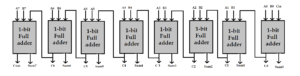
The 8-bit full adder block diagram:
 Now let's write, compile and simulate a VHDL program. Then we will get the waveform output and check it.
Before you begin, be sure to review the step-by-step procedure provided in VHDL Tutorial – 3 for designing the project. This will ensure that you correctly edit and compile the program and waveform file, as well as the final output.
For this project, we used a structural modeling style to build the 8-bit full adder circuit. A 1-bit full adder is used as a component.
VHDL Program
ieee library;
use ieee.std_logic_1164.all;
entity FA_8bit is
port(x,y: in std_logic_vector(7 to 0);
cin: in std_logic;
sum: out std_logic_vector(7 to 0);
co: std_logic output);
end FA_8bit;
FA_arch architecture of FA_8bit is
cary signal: std_logic_vector (6 to 0);
full_adder component is
port (p,q,r:in std_logic; sm,cr:out std_logic);
final component;
to start
a0:portmap full_adder (x(0),y(0),cin,sum(0),cary(0));
a1:portmap full_adder (x(1),y(1),cary(0),sum(1),cary(1));
a2:portmap full_adder (x(2),y(2),cary(1),sum(2),cary(2));
a3:portmap full_adder (x(3),y(3),cary(2),sum(3),cary(3));
a4:portmap full_adder (x(4),y(4),cary(3),sum(4),cary(4));
a5:portmap full_adder (x(5),y(5),cary(4),sum(5),cary(5));
a6:portmap full_adder (x(6),y(6),cary(5),sum(6),cary(6));
a7:portmap full_adder (x(7),y(7),cary(6),sum(7),co);
end FA_arch;
ieee library;
use ieee.std_logic_1164.all;
full_adder entity is
port (p,q,r:in std_logic; sm,cr:out std_logic);
end complete_adder;
FA_arc architecture of full_adder is
to start
sm <= p xor q xor r;
cr <= (peq) or (qer) or (rep);
end FA_arc;
It may be helpful to review the first two VHDL tutorials ( 1 and 2 ) in this series to refresh your memory on how this works.
Then compile the above program, creating and saving a waveform file with all required inputs and outputs listed (ensuring all different input combinations apply). Then simulate the project. You should get the following result…
Simulation waveform
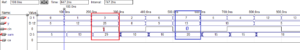
As can be seen in this figure, the sum of x, y and cin are highlighted in red and blue.
In the next tutorial, we will learn how to design a digital comparator using VHDL.