
What is VHDL?
- VHDL is a short form of VHSlC hardware description language, where VHSIC stands for Very High Speed Integrated Circuits
- It is a hardware description language – it means it describes the behavior of a digital circuit and can also be used to derive or implement a digital circuit/system hardware.
- It can be used for digital circuit synthesis and also for simulation.
- It is used to build digital systems/circuits using programmable logic devices like CPLD (Complex Programmable Logic Device) or FPGA (Field Programmable Gate Array)
- VHDL program (code) is used to implement digital circuit inside CPLD/FPGA, or it can be used to manufacture ASIC (Application Specific Integrated Circuit)
- It is very useful in developing sophisticated and sophisticated microprocessors or microcontrollers like ASIP (Application Specific Instruction Processor) or PSoC (Programmable System on Chip)
Now, before going into more details about VHDL, let us first see how and why there was a need for VHDL.
Why VHDL?
- In the 1980s, the US DoD (Department of Defense) began the VHSIC program
- Different hardware design companies started developing their ICs with their own HDL. All companies had their own different HDL
- So the problem is that all these different companies can't exchange their codes and designs with others.
- Additionally, all companies provide the chip design to the DoD with different HDL
- Therefore, there was a requirement for standardized hardware description language for design, documentation and verification of digital circuits/systems.
Advantages of VHDL
- It is supplier independent
- It's portable
- It is reusable
- It supports hierarchical design – an entire large, complex system can be modeled as an interconnection of small components, and again, components can be further modeled as an interconnection of subcomponents.
- All VHDL program instructions are executed simultaneously (unless and until the instructions are placed within a procedure, function, or process)
- It is readable by humans as well as machine
- It is IEEE and ANSI standard
- Supports different design methodologies such as top-down, bottom-up, mix, etc.
- It can be used to design combinational, sequential or mixed digital circuits using three different methods 1) data flow 2) behavioral 3) structural
Brief history of the origin of VHDL
- In 1985 the first version of VHDL 7.2 was developed by IBM, TEXAS INST. and Intermatrix under a DoD contract
- In 1987 it was standardized by IEEE with the IEEE 1076 standard. After that, the new IEEE 1164 standard was provided to VHDL, which is used everywhere today.
- ANSI also recognizes VHDL, and the VHDL standard reference manual is available from the IEEE which has an official description of this VHDL
Now, after getting enough information about VHDL, let's move on to designing digital circuits using VHDL.
Here again, before proceeding further, I advise you all to read two very good books on VHDL.
- Circuit design using VHDL by VA Pedroni
- A VHDL Primer by J Bhaskar
These books will provide complete information about VHDL and serve as companions on your journey to learn VHDL. The information provided above is also taken from these two books. I also encourage you to continually reference these books as you progress through this VHDL tutorial series.
So I think now you all are very excited to learn VHDL. Let's first see how to design a digital circuit using VHDL means, “ What is the VHDL design flow?”
VHDL design flow
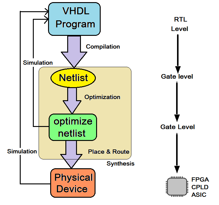
- The VHDL design flow starts with writing the VHDL program. Various manufacturing companies like XILINX, Altera, etc. provide their own software development tools like XILINX ISE, Altera Quartus, etc. In this VHDL code, the circuit is described in RTL (Resister Transfer Level)
- This VHDL code is compiled and generates Netlist at the Gate level. The compiler converts high-level VHDL code to RTL for Gate Level
- This Netlist is further optimized to get optimized Netlist again at the Gate level. Optimization is done for better speed and less space. The project simulation is done at this stage
- Finally, a physical device is implemented in CPLD/FPGA, or the final MASK is prepared for ASIC from this location-optimized Netlist and route software (fitter). once again the final device can be simulated and verified
This is the digital circuit design flow using VHDL. Now, since VHDL is also a type of programming language, it also has its program structure (similar to other programming languages such as C program structure). So, as a next step, let's learn what the structure of the VHDL program is.
VHDL program structure
- All VHDL programs consist of at least two components: Entity and Architecture
- May have additional components like configuration, package declaration, body, etc. as per requirements
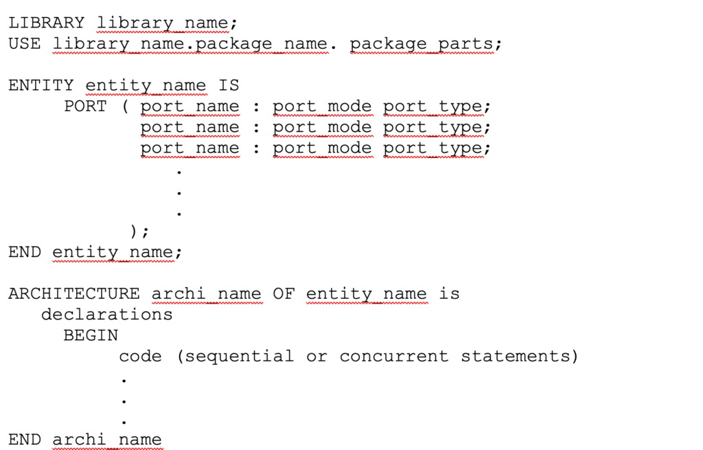
The structure of the VHDL program looks like:
 Library statement:
- The library contains all frequently used code. This will allow us to reuse them over and over again. Also this can be shared with other designs
- Starts with the keyword LIBRARY followed by the name of the library
- There are three libraries commonly used in all VHDL codes
- IEEE – specifies multilevel logical system
- std – resource library for VHDL design environment
- work – used to save our project work and program file (.vhd)
- However, in the program code, we only need to declare the IEEE library because the other two libraries are standard libraries
- Now to add library packages and their part, USE keyword is used with name of library, library packages and package parts. For example, in the IEEE library, the package is std_logic_1164 and to add its entire part we can write
IEEE LIBRARY
USE ieee.std_logic_1164.all
- Therefore, all VHDL programs start with the above two statements for library declaration
Entity statement:
- The entity defines digital circuit input-output connections with which it can interact with other components/circuits
- It states the number of inputs given to the circuit and the number of outputs taken from the circuit.
- Additionally, it declares any intermediate signals used in the circuit itself.
- The entity declaration begins with the ENTITY keyword. The user must provide the desired name for the entity, usually related to a circuit being designed such as ' mux,' ' decoder,' ' adder,' ' counter' etc. (the general rule for any VHDL program is that the program file name must be the same as the entity name)
- Within the entity, the input and output pins of a circuit are declared using the PORT keyword
- PORT (means interface pins) are declared with port_name, port_mode and port_type
- port_name – is a user-defined name of the input-output pin
- port_mode – there are four types of port mode IN, OUT, INOUT and BUFFER. IN indicates an input pin that can be read-only. OUT indicates an output pin and is write-only. Both pins are unidirectional. The INOUT pin is bidirectional and can be read and written. BUFFER is used for intermediate output
- port_type – can be BIT, BIT_VECTOR, STD_LOGIC, etc.
- After declaring all interfaces, the entity declaration ends with the END keyword followed by the entity name
- Let's look at an example entity for a two-input AND gate.

- Similarly, we can write an entity for half adder as

Architecture:
- Architecture declares the functionalities of the digital circuit
- Provides internal details of an entity, meaning how inputs and outputs are interconnected
- It describes the behavior of the circuit, means how the circuit generates the required output from given inputs
- The architecture declaration begins with the keyword ARCHITECTURE followed by architecture_name and entity_name
- The BEGIN keyword indicates the beginning of the architecture body. The body includes sequential or simultaneous instructions that describe the functionality of the circuit
- The architecture body ends with the END keyword followed by Architecture_name
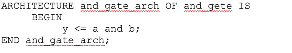
- Here is the architecture of 2 input AND gates (entity is given above).
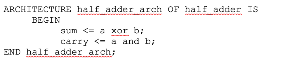
- Similarly, let's write an architecture for half adder.
- There are three different modeling styles for body architecture
- Data flow style – in this style of modeling the circuit is described using simultaneous instructions
- Behavioral style – in this style of modeling the circuit is described using sequential instructions
- Structural style – in this style of modeling the circuit is described using different interconnected components
- There can be one more styling style which is mixed styling style – a combination of any two or all three styles given above
This completes the fundamentals of VHDL, its design flow and program structure. In the next tutorial we will see different VHDL programs for digital circuits and different modeling styles for VHDL programs.