In this project I will interface the locks with the 8051 microcontroller (89c51, 89c52). I will interface 74LS574 with 8051(89c51, 89c52). You can also connect any other lock (74ls373, 74ls374 etc) with minor changes to the connections given in the circuit diagram. The entire project consists of capturing the status of the lock inputs and displaying them on a 40 × 4 character LCD screen when necessary.
What is Latch?
What is a lock? A latch is a flip-flop or combination of flip-flops that can store bits of data in it. A single flip-flop can store information a single bit at a time. Latches are used to build sequential circuits. The lock I'm using in this tutorial is 74ls574. It is an 8-bit lock, which means it can store 8-bit information at a time. It has 20 pins. A vcc applies +5v to it. GND lands. 8 input pins and 8 output pins. The two most important pins on the latches are OE and CP.
- CP- CP is clock pulse. When the CP is supplied with low to high (LH) pulse, the data on the input pins is stored in the latch's internal flip-flops.
-
OE-OE is the enable lock. When OE is done, the '0' data stored in the flip-flops appears on the output pins. When it is 1 nothing will appear in the output, it is void or GND.
Important Note: When I was working with this specific lock. what I observed is that when you leave any latch input pin empty, it means nothing is connected to the input pin. The output of that specific pin will appear high. I think in the default state the output pins are normally high. So make sure you don't use any input pins and ground them properly. Don't leave your circuit floating.
I used 74ls574 because of its simple one-way input and one-direction output. The photo below clearly clarifies the concept.
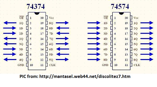
Pinout 74ls574 and 74ls374
What is the project doing?
Four latches are used in the design. They capture information from external inputs and pass it, one by one, to the 8051 microcontroller. Which then displays the latch output on a 40x4 character LCD. All latch outputs are connected to Port-0 of the 89c52 microcontroller.
8051 Latch Interface – Design Circuit
The microcontroller used in the Project is the 89c52 microcontroller. The 11.0592 MHz crystal is used in the design to generate clock pulses for microcontroller operation. The 40×4 character LCD is interfaced in 8-bit mode with the 89c51 microcontroller. The LCD data pins are connected to Port 1 of 89c52. LCD RS (Register-Select) control pins are connected to port 3 pin no. 2. RW (read-write) is connected to port 3 pin no. 1 of port 3. The activation of the second HD44780 LCD controller is connected to pin no. 3 of port 3.
Locks are enabled using Port-2. Pin #4 on port 2 activates the first lock, pin #5 the second, pin #6 the third, and pin #7 the fourth. All latches are connected to the Common Clock. CP is provided using Port 2 Pin #3.
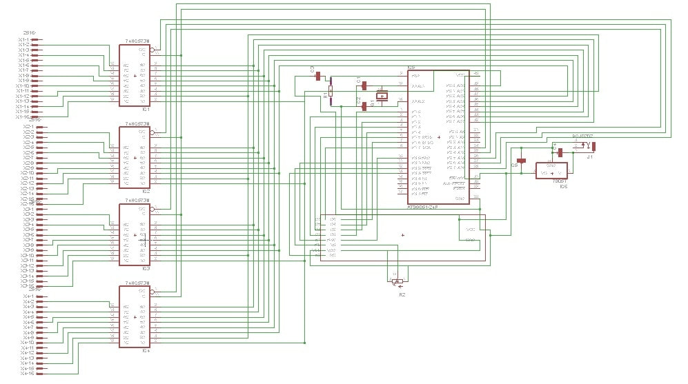
Locks with 8051 microcontroller
The circuit diagram above is not clear. It is made in proteaus circuit simulator. I have uploaded the proteaus files here so that you can easily visualize the circuit yourself in proteaus.
Circuit Diagram in Proteaus
I also designed the PCB of the above circuit. The final PCB circuit with electronic components installed is below. I etched the circuit by hand using etching chemicals. Drilling PCB holes and soldering components on PCB are also performed manually at home. Jumper wires are inserted into the latches. The output is connected directly to the registers of the 8051 microcontroller. See the traces of the lower half of the PCB.

Latches interlocked with 89c51 microcontroller final PCB
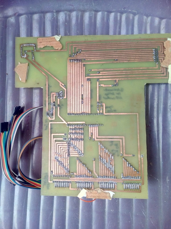
89c51 latches interface on the back of the PCB
Project working principle
For high (1) input on the latch, an up arrow will be displayed on the LCD for that specific input. For low (0) input on the latch, a down arrow will be displayed on the LCD for that specific input. The up and down arrows are generated in the LCD's CG-RAM. They are not text, so we first have to create them. I created them first in CG-RAM (character generated RAM) of the LCD and then displayed them on the LCD when needed.
- The string displayed on the first line of the LCD is " SMART PLC (programmable logic controller) ".
- The string displayed on the second line of the LCD is the status of the 1st and 2nd lock (up and down arrows)
- The string displayed on the third line of the LCD is the status of the 3rd and 4th lock (up and down arrows)
- The string displayed on the fourth line of the LCD is “ I/O Energized I/O Off “.
Final status of lc screen locks by 8051 microcontroller
Final result displayed on the LCD screen. The status of the locks is displayed on the 2nd and 3rd lines. Up arrow means the lock is active. At the lock, input voltage (5 volts) is present. The arrow pointing down means there is no voltage (0 v) at the lock input.
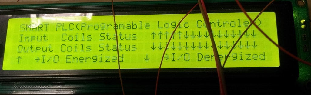
Locks with LCD display 8051 and 40×4
This project was a subpart of a larger project. I designed a PLC (Programmable Logic Controller) using microcontrollers. 8051 microcontroller latches are actually the status board in PLC design. The output from the main board is fed into the latches as input and then the status of the individual pins is displayed on the LCD. I recommend you take a look at the PLC project. You can consider the PLC project as your main final year project in electronics.
DIY PLC with microcontroller
Download the project files, Codes and Simulation, the folder contains the project hexadecimal code and other keil uvision files. The project simulation is also present in the folder. The simulation is done in Proteaus 8.0. You can write your questions below.
Locks with 89c51 microcontroller