UMPS is perhaps the most efficient virtual simulator for simulating 8051/52/2051/4051 programs, PIC microcontrollers, HC microcontrollers, AVR microcontrollers, etc. It has a wide variety of peripherals to connect with microcontrollers such as LED, matrix LED, alphanumeric display, all types of LCD, etc. Other peripherals like ADC, DAC, serial transceiver, function generator, I2C memory, I2C Display, PWM converter, digital recorder and player, shift register, etc. are provided to design any embedded system. With the help of referees, you can create a virtual 8051 training board on your computer desktop. It can simulate all types of programs by connecting necessary features like 7-segment display, Matrix LED, LCD, Matrix keyboard and anything you want.
Click here to download zip folder for this software
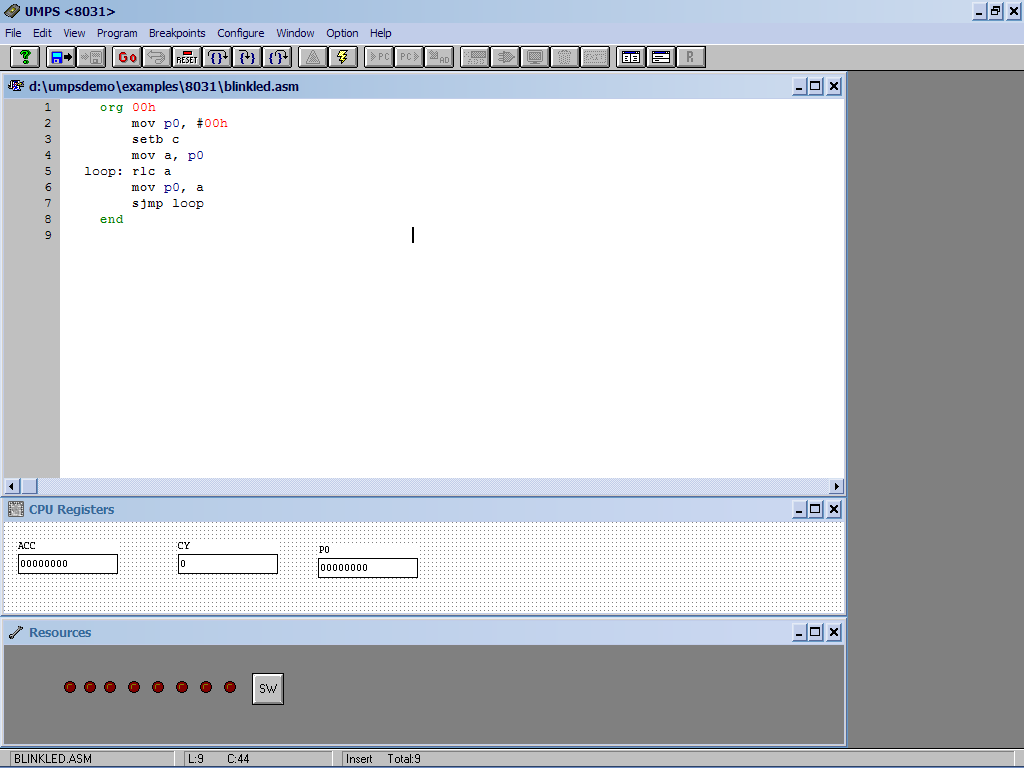
Here I explained an example in which you can easily understand how the UMPS software works. It describes how to edit the build and run a simple blinking LED program on port P0. It also explains how to connect LEDs to the port and see the chasing effect on them.
First open the UMPS program from the Start menu -> all programs-> demo umps 1.91-> demo umps 1.91. You will see below screen.

Configuring CPU
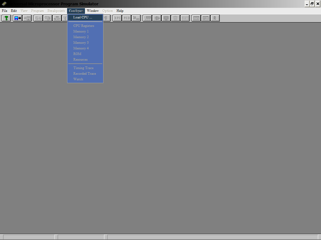
Now first you need to load the pre-compiled CPU file available in the configuration menu. Then open configure -> load CPU

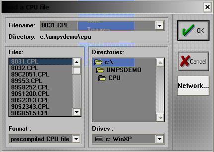
You will be prompted to load the desired CPU from all the given CPUs. Since you need to work with 8051 assembly language, select the 8031.cpl or 8032.cpl file and click OK.
You will see the following message on your screen. Click OK.
Writing Program
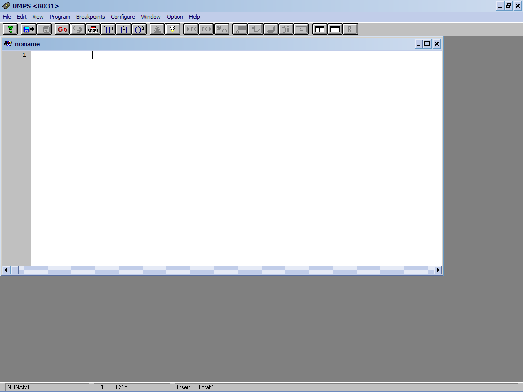
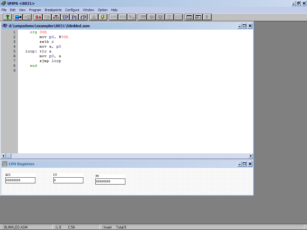
Now you will see that all menus are enabled. Now from the file menu click on new file to create a new file or you can open any existing file from the open file tag. If you select a new file, the editor area will open where you can write the program.
Write a simple program for blinking LEDs on port P0 as given
organization 00h
movement p0, #00h
bc set
movement a, p0
loop: rlc a
movement p0, a
sjmp loop
end
You will see that the org and end mnemonics are highlighted in bold green and all other opcodes like mov, rlc, sjmp etc. are highlighted. Now save the file with the name “blinkled.asm” in any specific directory or folder. Then open the program menu and select compile (or just press ctrl+F9). Go to your directory or folder and in the list find out “blinkled.asm”. Click OK.
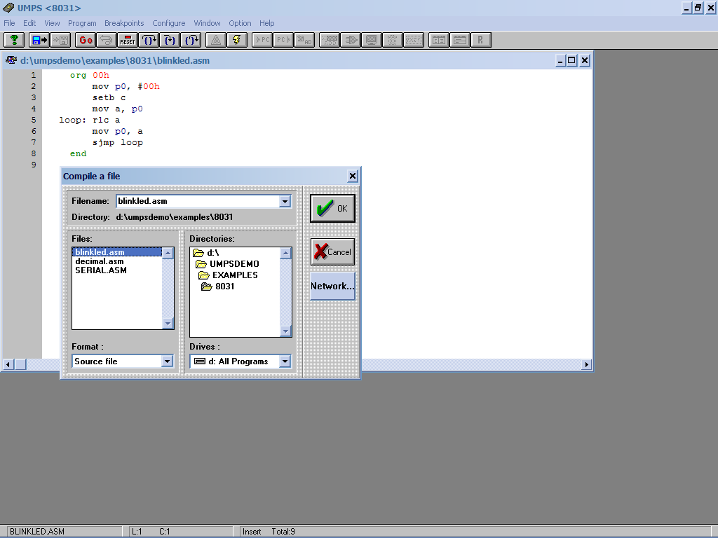
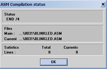
You will see a message box showing the build status. If there is no error it will show “END” otherwise it will indicate an error with line number and type of error. Resolve the error and compile again.
Program running
After compilation, we will run the program. But before that we have to restart the CPU by pressing ' RESET ' button

at the toll bar. There are many options provided to run the program like step over, enter,

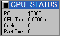
go (run) etc. So if you want to run the program step by step, press the step by step button on the toll bar. You will see that the program is running step by step. In the status bar you can see the CPU time and the number of cycles executed (both things can be viewed in the view->CPU status menu).
Now to see the output go to configure->CPU register. The CPU log window will appear on the screen. Then click on the 'add' button and you will see the list of all records appear on the screen.
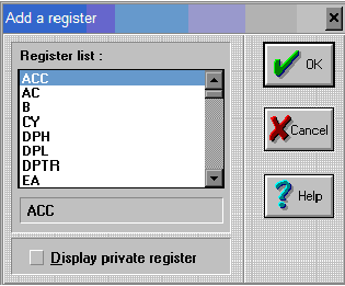
Select P0, Acc and CY registers one by one as shown in the figure.
Now, when you run the program, you will see the P0, CY and ACC values change. If you right-click on any record, a pop-up menu will appear to change the base to decimal, binary or hexadecimal.

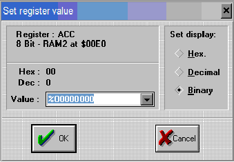
If you double click on register, a window for changing the register value will appear.
If you activate the CPU log window by clicking configure->CPU log and double click on any register, the following window will appear.
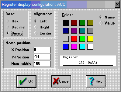
From here you can change the record name color setting, as well as the value, its alignment, base name position, width, etc.
Selecting Resource
Still, we want to see the actual output appearing at port P0 indicated by LEDs. Then we have to connect the LEDs to the P0 port. To do this, select the resources in the configuration window. The resources window will open. Then click on the add button and you will see various features like LED, seven-segment display, button, LCD, ADC and more.
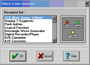
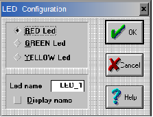
Select eight LEDs one by one. Double clicking on any LED will display the following window. Using this window you can change the LED color as well as the name.
Select an LED and click connect

button. The following window will appear.
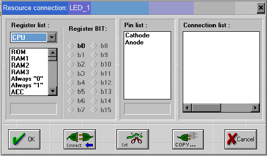
You will see that the anode and cathode terminals of the LED are provided. Now scroll down the CPU log window and select P0. Select 'b0' in register bit. Then select the LED anode and click connect. Connect the cathode with 'always 0' and click OK. Do the same thing for all the LEDs and connect them from 'b1' to 'b7' respectively. Now when you run the program you can see the chasing effect on the LED.
Editing code
Let's add one more thing to the program. Edit the code as given below
organization 00h
movement p0, #00h
bc set
wait: jb p1.0, wait
movement a, p0
loop: rlc a
movement p0, a
sjmp loop
end
Now the program will wait in the loop until pin p1.0 is high. As it becomes low, the chasing effect will begin. Again compile the program and restart the CPU. Now in step mode, the program will stop at this instruction and keep repeating the loop until the p1.0 pin goes low. To decrease it, we will connect a push button to this pin. So, again select the features tab in the configuration menu and click the Add button. This time select the button from the menu. By double-clicking the button, the following window will appear.
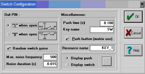
You can set all the key properties like name, display, connection type, etc., configure the key as you want. Then click the connect button and you will see this window.
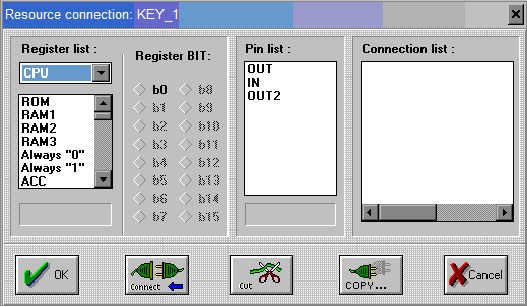
There will be two or three pins on the key. Select 'in' and connect it will be 'always 0'. Select 'out' (or 'out2') and connect it with 'b0' of P1. Click OK. Now continue running the program again. The program is still repeating the same loop. But when you press the button in the next step, the program breaks out of the loop and starts chasing the effect.
You can also add the P1 register in the CPU register window. To do this, activate the CPU log window by selecting configure->CPU log window. Then click on the add button and select P1 in the window. Now the complete window will look as shown.
Here I explained the use of referees with just one example. But it is possible to connect all the resources given in the resources window with 8051. For proper connection and operation of any resource you can always take the help of umps. To do this, click on help -> index -> resources. You can get a simplified datasheet and some useful information about this feature. Use this information and connect any resource to the 8051.
So go ahead….. ALL THE BEST!!!
Project source code