The various constants of the induction motor equivalent circuit can be determined as follows:
Determination of G Ó and B Ó and, therefore, R Ó and X Ó
To find out G Ó and B Ó The induction motor is brought to synchronous speed using another machine. The additional machine helps compensate for frictional losses and air resistance. Under these conditions the slip s = 0 and the current consumed by the induction motor is I Ó only as s = 0, the term R M =R 2 {(1/s)-1)} becomes the load resistance R M =0. This test uses the wattmeter reading
C=3G Ó v 2 ,
Where,
V is the supply voltage.
Therefore G Ó = C/3V 2
Furthermore, the no-load current is I 0 = VY Ó
Therefore, you Ó =I Ó /V
b Ó = √ (S Ó 2 – G Ó 2)
Here g Ó is the exciting conductor and B Ó is the stimulating susceptibility. If you know these values R Ó and X Ó be determined. These sizes are necessary to design the equivalent circuit.
Normally it is not possible to operate the induction motor at synchronous speed. If it is coupled to another motor and its speed can be varied up to the synchronous speed of the induction motor, it works without mechanical effort. The speed is assumed as synchronous speed. With this assumption the G Ó and B Ó can be determined as described below.
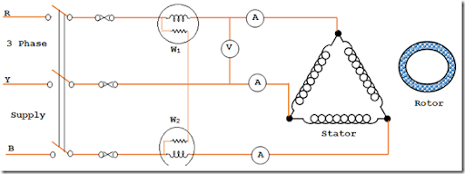
Idle Test
The connection diagram for no-load testing of three-phase induction motor is shown above. The wattmeter, ammeter and voltmeter readings are read. The total energy consumption is given by the two wattmeters W. 1 and W 2 .
Let total input power = W. 0 watt
No-load input current = I 0 amplifier
Applied voltage = V Ó volt
When idle, input power is supplied to compensate for losses.
1. Loss in stator winding 3I Ó 2 R 1
2. Loss of 3G Ó v 2 core
3. Friction losses and air resistance.
Core losses, friction losses, and wind losses are collectively called fixed losses.
As the total power consumed is known and is W Ó E
b Ó = √3V M EU 0 CosΦ 0
From this relationship
CosΦ Ó = W / √3V M EU 0
Where V M = mains voltage
EU 0 = idle input current
b 0 = input power at idle
From this test I C Ó CosΦ Ó be observed and identified.
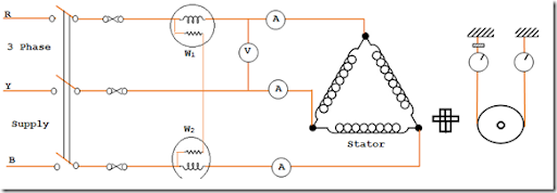
Locked Rotor Test
This test is also known as a stopped rotor test or a short circuit test. The connection diagram of the lock rotor test in a three-phase induction motor is shown in the figure.
During this test, the rotor is blocked (cannot rotate or only at a very low speed). In a slip ring motor, the rotor windings are short-circuited to the slip rings. A reduced voltage, almost 15% of the normal voltage, is applied to the stator winding. The voltage is adjusted so that the stator windings can be supplied with full load current.
The power consumption, i.e. the current voltage, is measured using the measuring devices connected to the circuit. They are V S the short-circuit voltage, L S Short-circuit current with voltage V S and W S Total power that the motor consumes in the event of a short circuit.
The following is calculated from the measured values:
1. Short-circuit current in relation to the normal stator supply voltage.
It's me SN = me S x (V/V S )
Where
EU SN = short-circuit current related to normal voltage
v S = Reduced voltage present during short circuit
EU S = Short circuit current when voltage is applied during short circuit
V = Normal supply voltage for the stator winding
2. Power Factor Locked Rotor Test
It is determined as, b S = √3V S EU S CosΦ S
Therefore CosΦ S = W S /√3V S EU S
Where W S = Total motor energy consumption in case of short circuit
V = Voltage applied during short circuit
EU S = current in case of short circuit
3. Leakage resistance and reactance values
During the locked rotor test, the motor input is fed against stator copper losses, rotor copper losses, and core losses. As the voltage is very low in this test, the core loss is very small and can be neglected.
Therefore, total copper loss = W S
b S = 3I 2 S R 01
So R is 01 = W S /3I 2 S —-> 1
Knowledge of the values of V S and I S Z o1 is calculated as
Z o1 =V S /I S —–> 2
Z 01 = √ (Z 2 01 -R 2 01)
With equations 1 and 2
To find X 1 and X 2 It is generally assumed that X 1 =X 2 '
Therefore, X is 1 =X 2 ' =X 01 /2
How to determine the value of R1 and R2'
For a squirrel cage rotor, R1 is determined by suitable tests on the stator windings. Then subtract R 1 by R 01 the value R 2 ' is received.
In the case of a wound rotor, R 1 and R 2 'are determined by knowing the resistance ratio of the stator and rotor windings.
In the expression given above
R 01 = Stator and rotor motor winding in phase with respect to the stator
Z o1 = Motor impedance per phase in relation to the stator
X 01 = Motor leakage reactance per phase related to the stator
R 1 = stator resistance per phase
R 2 ' = Rotor resistance per phase based on stator
X 1 = stator reactance per phase
X 2 ' = Reactance of the rotor per phase related to the stator
From the test data obtained from the no-load test and the stall test of the three-phase induction motor, the above-mentioned constants are determined. These constants are used to develop the equivalent circuit of the three-phase induction motor and construct the circular diagram.
Conclusion
In summary, the idle test and stall test are important diagnostic tools for evaluating the performance and health of an induction motor. No-load testing allows us to determine core losses and magnetizing current to optimize energy efficiency. Stall testing, on the other hand, helps you understand the engine's starting characteristics and identify potential failures. Both tests help you make informed decisions regarding engine operation, maintenance and replacement. Overall, its proper implementation guarantees the reliable and efficient operation of induction motors and contributes to improving industrial productivity and energy savings.