Backward slope (Y b ): This is the distance, measured relative to the armature winding, between the two sides of a coil at the rear of the armature, as shown in Fig. YB. . For example, if a coil connects conductor one (top conductor in one slot) to conductor twelve (bottom conductor in another slot) at the back of the coil, then the back pitch is S b =12-1=11 conductors .
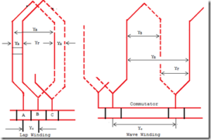
Front pitch (Y F ): It is the distance, measured in relation to the armature winding, between the sides of the coil connected to any segment of the commutator shown in the figure. It is denoted by Y. F. For example, if sides twelve and three of the coil are connected to equivalent segments of the commutator, the front pitch will be S F =12-3=9 conductors.
Resulting slope (Y R ): It is the distance (measured in anchor conductors) between a conductor and the opening of the subsequent conductors to which it is connected; shown in Fig. YR refers to them. Therefore, the resulting pitch is the pure mathematical sum of the back and front pitches.
Commutator division (Y C ): This is the number of commutator segments that are covered by each coil of the armature winding.
Progressive Winding: A progressive winding is a winding in which the connections to the commutator, drawn collectively through the winding, can extend around the machine in the same direction as the path of each individual coil.
Retrogressive winding: A retrograde winding is a winding in which the connections to the commutator on the machine run in the opposite direction, i.e. along the path of each individual coil.
Conclusion
As we delve deeper into armature winding terminology, we develop a deep appreciation for the complex language underlying the field of electrical machines. The vocabulary we learned in this article serves as a thread that weaves together the complex mesh of armature windings, allowing for the generation of electromagnetic energy and efficient energy conversion.