
Sequence timer is used in many manufacturing industries to turn ON and OFF processes one by one automatically. Sequence timer is needed at most when there is chain of processes – means 1st process ends, it triggers 2nd process, when 2nd ends, it triggers 3rd process and so on (like chain reaction!!!…. ). The times and durations of each process must be defined initially. Each process requires a specific duration of time. The duration of each chain process is defined (scheduled) before the entire chain process begins. Then the 1 st process is triggered. It runs for a set duration and when it finishes, 2 and the process begins and so the chain begins. Each process runs for a defined duration and when it finishes, it activates the next process. This continues until the last process. There may be several such processes. When the last process finishes, the chain stops. If it is in continuous or repeat mode, again 1 st the process will start and this cycle will repeat continuously.
Examples of such a process can be found in the metal fabrication or welding industries. In the welding process there are four sub-processes that must be activated one after the other. (1) the work (to be welded) is placed under the electrodes via the conveyor (or by any other means) (2) the electrodes compress the work to apply suitable pressure (3) the contactor is turned on to pass current through of electrodes and work (4) finally the work is put under pressure to be welded correctly. All these processes are triggered one after the other and each process requires a specific time. The time durations for each process are initially defined and then the process is started.
Here, the presented project demonstrates such a sequence timer with real-time clock chip. It uses Arduino microcontroller and DS1307 RTC chip to set the real time and duration of processes. The duration of the process can be set in hours, minutes and seconds. The process runs in real time according to the time provided by the RTC chip. There is 16×4 LCD in the design to display the process status, other different messages and in real time. The user can define and schedule the process start time and duration of 3 different sub-processes. In this demonstration, 3 relays are turned ON and OFF in sequence and it is assumed that the relay will ON and OFF the process. So, let's first see the circuit diagram and its working followed by the program.
Circuit Diagram:
Circuit Description:
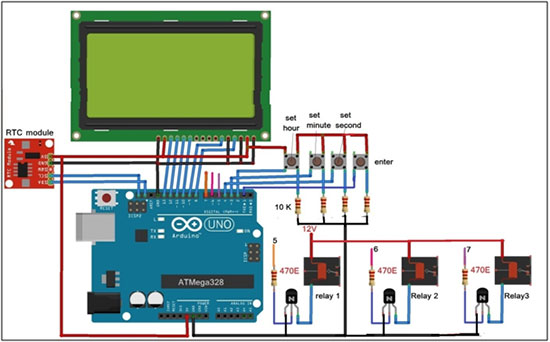
As shown in the above figure, the circuit is built using RTC DS1307 chip module, 16×4 LCD, Arduino UNO board and some other components like buttons, relays, transistors, resistors etc.
· The RTC module has four-wire interface Vcc, Gnd, SDA and SCL. Vcc and Gnd pins are connected to the Arduino board 5V and Gnd respectively which provides bias voltage for its operation
· The SCL and SDA pins are connected to the SCL and SDA pins of the Arduino. Arduino communicates with the RTC DS1307 chip using these two pins
· Four buttons are connected to digital pins 1, 2, 3 and 4 of the Arduino. All buttons are pulled to ground via 10K resistors as shown. when any button is pressed, the respective Arduino pin gets logic input 1 (HIGH)
· Digital pins 5, 6 and 7 activate three 12 V relays through 3 NPN type transistors as shown. The relay coils are connected between the external 12 V source and the collector terminals of the transistor
· Three different devices (not shown in the figure) are connected with relay contact terminals. It means the device is on when the relay is on. The device reassembles any industry process.
· Data pins D4-D7 of LCD are connected to pins 10 – 13 of Arduino. Two control pins Rs and En are connected to pins 8 and 9 respectively. The RW and VEE (contrast control) control pins are connected to ground
LCD backlight LED receives 5V power
Circuit Operation:
· When power is supplied to the circuit through USB, initially all three relays and hence the devices are switched off. The person must first define the times for each device (process)
· The initial message is displayed on the LCD as “ Set sequence start time ”
· Now the person needs to set the start time of the sequence # in hours, minutes and seconds using buttons. Data 4 buttons have the following functions.
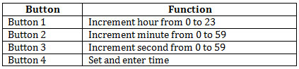
. So, by pressing button 1, button 2 and button 3, the person will set the required hour, minute and second and then press the Enter button to set the start time of the sequence
· The message is displayed on the LCD as “ Sequence start time is set to XX:XX:XX ” (this is the actual time when the sequential process will start) ·
· Next, person is asked to enter process duration 1 in hour , minute and second. LCD displays message “ Set process duration 1 to 00:00:00 ”
· Again, the person must enter the total duration of process 1 in hours, minutes and seconds – this means how long process 1 will run.
· One must set duration* (not time!!!!!) for process 1 using buttons. When the duration is set and the Enter button is pressed, the message is displayed on the LCD as “ The duration of process 1 is XX hour XX minute and XX sec. ”
· Similarly, the person must define the duration of process 2 and process 3 as well. When the duration is set, a similar message is displayed on the LCD as “ The duration of process X is XX hour XX minute and XX sec. ”
· When all 3 process durations are set and the Enter button is pressed, the actual operation of the circuit begins
· Arduino reads the current time from the RTC module and displays it on the LCD as “ Time: – XX:XX:XX ”. Along with this LCD also displays the start time of process 1 (the start time of the sequence that the user has entered)
· It then continuously compares the current time and the start time of process 1. When they coincide, it turns on the first relay and thus process 1 by sending logic HIGH (1) on digital pin 5. The message displayed on the LCD how “ process 1 begins ”
· The LCD also displays the message “ process 2 start time xx:xx:xx ” – this is the actual time that process 1 will end and process 2 will begin
· Now again, Arduino compares the current time with the start time of process 2. When both match, it first turns off 1st relay and turns on 2nd relay. Then 2 and the process starts. The LCD displays “ process 2 starts ” and “ Process 3 start time xx:xx:xx ”
· Again when the current time is equal to the start time of process 3, 2nd relay is turned off and 3rd relay is turned on to start 3rd process.
· The LCD displays “ process 3 starts ” and the last message on the LCD is “ process 3 end time xx:xx:xx ”
· Finally, when the end time of process 3 is reached, 3rd the relay is also switched off and thus the complete sequence is completed
# Note 1: Sequence start time means user has to enter the actual time at which the entire sequential process will be started. He has to enter the desired actual time like 10:00:00 (am) or 15:30:00 (pm) when he wants process to be started .
* Note 2: process duration means how long the process will take to complete . Here the user has to enter process duration is not the time
This is how the sequential timer starts the process one by one according to the programmed time and duration. Here is the snap of the circuit arrangement

Project source code
###
//Program to #include#include "RTClib.h" #include #include #define set_hr 1 #define set_min 2 #define set_sec 3 #define enter 4 #define device1 5 #define device2 6 #define device3 7 LiquidCrystal LCD(8, 9, 10, 11, 12, 13); RTC_DS1307 rtc; int hr=0, minut=0,sec=0,set_time_flag=1,sys_en_flag=0; int process1_time_flag=0,process2_time_flag=0,process3_time_flag=0; int process1_hr,process1_min,process1_sec; int process2_hr,process2_min,process2_sec; int process3_hr,process3_min,process3_sec; int strt_hr,strt_min,strt_sec,time_flag=1; void setup { Serial.begin(9600); lcd.begin(16, 4); lcd.clear; pinMode(set_hr,INPUT); pinMode(set_min,INPUT); pinMode(set_sec,INPUT); pinMode(enter,INPUT); pinMode(device1,OUTPUT); pinMode(device2,OUTPUT); pinMode(device3,OUTPUT); digitalWrite(device1,LOW); digitalWrite(device2,LOW); digitalWrite(device3,LOW); } void loop { int hr_set_but,min_set_but,ent_but,sec_set_but; hr_set_but = digitalRead(set_hr); min_set_but = digitalRead(set_min); sec_set_but = digitalRead(set_sec); ent_but = digitalRead(enter); ///////////////// turn device ON or OFF //////////////////////////// //// if(time_flag) { DateTime now = rtc.now; lcd.print("current time is"); lcd.setCursor(0,1); lcd.print(now.hour ); lcd.print(':'); lcd.print(now.minute ); lcd.print(':'); lcd.print(now.second ); delay(3000); lcd.clear; lcd.print("Set sequence "); lcd.setCursor(0,1); lcd.print("start time:"); lcd.setCursor(0,2); lcd.print("00:00:00"); time_flag=0; } if(sys_en_flag) { DateTime now = rtc.now; ///////////// display current time on LCD ////////////////////////// lcd.setCursor(6,0); lcd.print(" "); lcd.setCursor(6,0); lcd.print(now.hour ); lcd.print(':'); lcd.print(now.minute ); lcd.print(':'); lcd.print(now.second ); if(now.hour ==EEPROM.read(11) && now.minute ==EEPROM.read(12) && now.second ==EEPROM.read(13)) { digitalWrite(device1,HIGH); lcd.setCursor(8,1); lcd.print('2'); lcd.setCursor(6,2); lcd.print(EEPROM.read(14)); lcd.print(':'); lcd.print(EEPROM.read(15)); lcd.print(':'); lcd.print(EEPROM.read(16)); lcd.setCursor(0,3); lcd.print("Process 1 starts"); } if(now.hour ==EEPROM.read(14) && now.minute ==EEPROM.read(15) && now.second ==EEPROM.read(16)) { digitalWrite(device1,LOW); digitalWrite(device2,HIGH); lcd.setCursor(8,1); lcd.print('3'); lcd.setCursor(6,2); lcd.print(EEPROM.read(17)); lcd.print(':'); lcd.print(EEPROM.read(18)); lcd.print(':'); lcd.print(EEPROM.read(19)); lcd.setCursor(0,3); lcd.print("Process 2 starts"); } if(now.hour ==EEPROM.read(17) && now.minute ==EEPROM.read(18) && now.second ==EEPROM.read(19)) { digitalWrite(device2,LOW); digitalWrite(device3,HIGH); lcd.setCursor(8,1); lcd.print("3 end "); lcd.setCursor(6,2); lcd.print(EEPROM.read(20)); lcd.print(':'); lcd.print(EEPROM.read(21)); lcd.print(':'); lcd.print(EEPROM.read(22)); lcd.setCursor(0,3); lcd.print("Process 3 starts"); } if(now.hour ==EEPROM.read(20) && now.minute ==EEPROM.read(21) && now.second ==EEPROM.read(22)) { digitalWrite(device3,LOW); lcd.setCursor(0,3); lcd.print("Process 3 ends "); } delay(1000); } ///////////// set ON time and OFF time for device /////////////////// if(hr_set_but) { if(hr<24) hr++; if(hr==24) hr=0; lcd.setCursor(0,2); lcd.print(" "); lcd.setCursor(0,2); lcd.print(hr); delay(200); } if(min_set_but) { if(minute<60) minute++; if(minute==60) minute=0; lcd.setCursor(3,2); lcd.print(" "); lcd.setCursor(3,2); lcd.print(minute); delay(200); } if(sec_set_but) { if(sec<60) sec++; if(sec==60) sec=0; lcd.setCursor(6,2); lcd.print(" "); lcd.setCursor(6 ,2); lcd.print(sec); delay(200); } if(ent_but) { if(set_time_flag==1) { strt_hr=hr; strt_min = minute; strt_sec = sec; EEPROM.write(11,strt_hr); EEPROM.write(12,strt_min); EEPROM.write(13,strt_sec); set_time_flag=0; process1_time_flag=1; lcd.setCursor(0,0); lcd.print("sequence start "); lcd.setCursor(0,1); lcd.print("time is set to "); lcd.setCursor(0,2); lcd.print(strt_hr); lcd.print(':'); lcd.print(strt_min); lcd.print(':'); lcd.print(strt_sec); delay(2000); lcd.setCursor(0,0); lcd.print("Set Process 1 "); lcd.setCursor(0,1); lcd.print("Time duration "); lcd.setCursor(0,2); lcd.print("00:00:00"); hr = 0; minute = 0; sec = 0; } else if(process1_time_flag==1) { process1_sec = sec + EEPROM.read(13); if(process1_sec>60) { process1_sec = process1_sec-60; minute++; } process1_min = minut+EEPROM.read(12); if(process1_min>60) { process1_min = process1_min-60; hr++; } process1_hr = hr+EEPROM.read(11); EEPROM.write(14,process1_hr); EEPROM.write(15,process1_min); EEPROM.write(16,process1_sec); process1_time_flag=0; process2_time_flag=1; lcd.setCursor(0,0); lcd.print("Process 1 time "); lcd.setCursor(0,1); lcd.print("duration is "); lcd.setCursor(0,2); lcd.print(hr); lcd.print("Hr"); lcd.print(minute); lcd.print("minute"); lcd.setCursor(0,3); lcd.print("and "); lcd.print(sec); lcd.print("sec"); delay(2000); lcd.clear; lcd.setCursor(0,0); lcd.print("Set Process 2 "); lcd.setCursor(0,1); lcd.print("Time duration "); lcd.setCursor(0,2); lcd.print("00:00:00"); hr = 0; minute = 0; sec = 0; } else if(process2_time_flag==1) { process2_sec = sec + EEPROM.read(16); if(process2_sec>60) { process2_sec = process2_sec-60; minute++; } process2_min = minut+EEPROM.read(15); if(process2_min>60) { process2_min = process2_min-60; hr++; } process2_hr = hr+EEPROM.read(14); EEPROM.write(17,process2_hr); EEPROM.write(18,process2_min); EEPROM.write(19,process2_sec); process2_time_flag=0; process3_time_flag=1; lcd.setCursor(0,0); lcd.print("Process 2 time "); lcd.setCursor(0,1); lcd.print("duration is "); lcd.setCursor(0,2); lcd.print(hr); lcd.print("Hr"); lcd.print(minute); lcd.print(" mn "); lcd.setCursor(0,3); lcd.print("and "); lcd.print(sec); lcd.print("sec"); delay(2000); lcd.clear; lcd.setCursor(0,0); lcd.print("Set Process 3 "); lcd.setCursor(0,1); lcd.print("Time duration "); lcd.setCursor(0,2); lcd.print("00:00:00"); hr = 0; minute = 0; sec = 0; } else if(process3_time_flag==1) { process3_sec = sec + EEPROM.read(19); if(process3_sec>60) { process3_sec = process3_sec-60; minute++; } process3_min = minut+EEPROM.read(18); if(process3_min>60) { process3_min = process3_min-60; hr++; } process3_hr = hr+EEPROM.read(17); EEPROM.write(20,process3_hr); EEPROM.write(21,process3_min); EEPROM.write(22,process3_sec); process3_time_flag=0; lcd.setCursor(0,0); lcd.print("Process 3 time "); lcd.setCursor(0,1); lcd.print("duration is "); lcd.setCursor(0,2); lcd.print(hr); lcd.print("Hr"); lcd.print(minute); lcd.print(" mn "); lcd.setCursor(0,3); lcd.print("and "); lcd.print(sec); lcd.print("sec"); delay(2000); lcd.clear; lcd.print("Time:-"); lcd.setCursor(0,1); lcd.print("Process 1 Start "); lcd.setCursor(0,2); lcd.print("Time: "); lcd.print(strt_hr); lcd.print(':'); lcd.print(strt_min); lcd.print(':'); lcd.print(strt_sec); sys_en_flag=1; } } } ###
Circuit diagrams
| Industrial Sequence Timer Using RTC and Arduino_circuit-Diagram |  |
Project video


