
Manufacturing or processing industries such as textile, chemical, pharmaceutical and others have many continuous processes that require monitoring and record keeping of different physical parameters such as temperature, humidity, pH, humidity, flow rate, viscosity, etc. are continuously displayed and stored on mainframe computers. Modern industries have DCS and SCADA systems to monitor, store and control these parameters. With the latest technology, Industry 4.0 with IoT technology, these parameters are monitored and stored in the cloud.
Physical parameters are detected using transducers (sensors), and their value is converted into digital. This digitized value is then stored in the computer's memory (hard drive) or semiconductor memory chip. To maintain an accurate data record, the sensor value is stored with a timestamp (the value of the physical quantity detected by the sensor at a specific time and date (i.e. temperature: 45 ó C Time: 16:05 :10, Date: 11/23/2022). This record is displayed on a computer monitor or any other display device at any time and whenever necessary.
This project demonstrates a simple system where I used a temperature sensor and stored temperature readings on a serial memory chip. It also uses a real-time clock (RTC) to keep records of temperature readings with time and date, and also communicates with a computer to display this record on a monitor.
The system uses an Arduino microcontroller board with IIC 24C32 memory and a DS1307 module with RTC chip.
System block diagram
The main building blocks of the system are a temperature sensor, RTC DS1307 chip, IIC 24C32 serial memory, an Arduino microcontroller board and a computer.
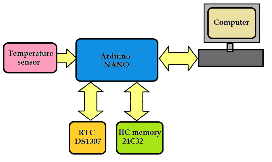
Temperature sensor: detects temperature and provides analog output voltage per temperature change.
DS1307 RTC chip: has a 100-year calendar from 2000 to 2100 and provides accurate time and date with the day. It is used to provide time and date with sensor reading to store records properly
IIC 24C32 serial memory : used to store (record) data (sensor value – temperature readings) with time and date
Arduino NANO board: the main building block of the system. It has an 8-bit ATMega328 microcontroller with 32 KB of FLASH and performs the following tasks:
- Reads the temperature from the sensor and converts it to a digital value
- Reads time and date from RTC chip
- Write the sensor value with time and date into the serial memory every five seconds.
- Displays stored sensor readings, time and date on the computer's serial monitor
Computer: Used to monitor temperature readings and display stored temperature records with time and date.
Before we move on to the schematic diagram, its functioning and operation, let us first collect the necessary items.
Required Items
Analog and digital temperature sensor module

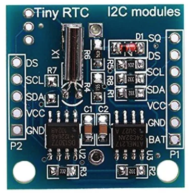
IIC memory and RTC module DS1307
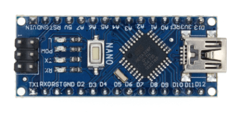
Arduino NANO board
Schematic diagram
 Description
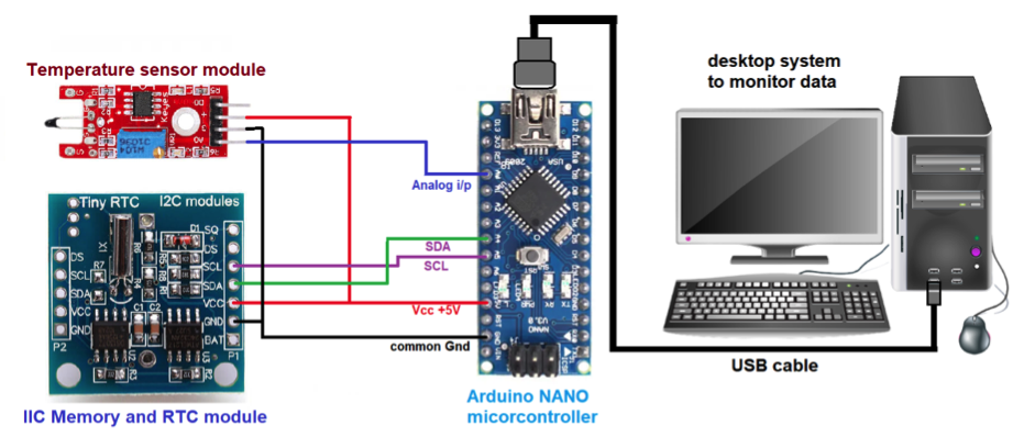
The figure shows that the complete system is built using just three components (or modules) – temperature sensor module, IIC memory, RTC module and Arduino nano board.
- The temperature sensor module has four interface pins. (1) +V, (2) G, (3) A0 and (4) D0. The +V pin is connected to the +5V output pin of the Arduino board. Pin G is connected to the common ground of the circuit. The A0 analog output pin is connected to the A0 analog input pin of the Arduino board. Digital output pin D0 is not used here.
- The IIC memory and RTC module have many interface pins, of which only four are used. (10 Vdc, (2) Gnd, (3) SDA and (4) SCL. The Vcc pin is connected to the +5 V output pin of the Arduino board and the Gnd pin is connected to the common ground of the circuit. The SDA pins and SCL are connected to I2C pins A4 and A5 on the Arduino board, respectively
- The Arduino board communicates via a USB data cable with the main computer system. Sensor data is monitored on a serial monitor.
- The Arduino board and modules receive +5V power from the main computer via a USB cable.
Here is a photo of the circuit arrangement.

Work and operation
The module consists of a comparator with potentiometer. The temperature sensor is an NTC thermistor; its resistance changes with a change in temperature. The change in resistance is converted to an analog voltage output. This analog output voltage is available on pin A0. Thus, the module provides an analog production voltage as the temperature changes.
This analog voltage receives input to the internal ADC of the Arduino microcontroller, which reads this analog voltage and converts it into a digital value. The Arduino then reads the timestamp in the format HH:MM:SS, DD/MM/YYYY from the RTC DS1307 chip via the IIC SDA and SCL pins. It then stores the digital value of the sensor reading in the IIC 24C32 memory with time and date.
The Arduino continues to read the value from the sensor and stores it in memory with time and date after every second. This process repeats until the 32 KB memory is full. After that, the sensor data is overwritten from the first memory location.
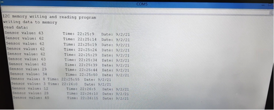
To read the data stored in memory at any time, it is necessary to send the “r” command from the serial monitor (computer) to the Arduino through serial communication. When Arduino receives this command, it reads all the data stored in memory and displays it on the serial monitor as a temperature value at a given time and date.
Here is a picture of the output on the serial monitor screen.
Software program
The program is written in Arduino IDE and compiled and loaded into the internal Flash of the Arduino ATMega328 microcontroller. The program uses Arduino's built-in wire library “wire.h” and RTC library “RTCLib.h” in the program. The “wire” library functions are used to write and read data from IIC serial memory.
Here is the YouTube video link for this article