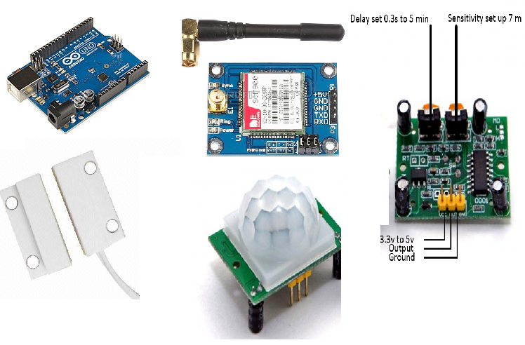
PIR Motion Detection Sensor
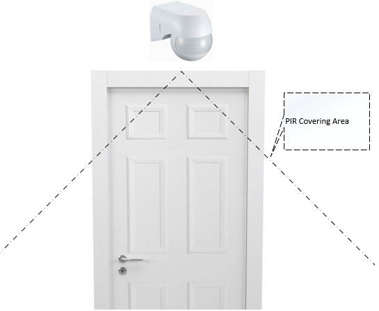
So where will the pir sensor be mounted to detect the presence of a person. It must be mounted on the top of the door entry. The diagram below better illustrates the PIR mounting above the door.
Sim900 Gsm Module (Arduino Gsm)
All sim900 gsm modules communicate with external controllers/microcontrollers over Uart protocol. The Uart protocol has two pins. One is TxD (Transmit) and another is RxD (Receive). To send and receive data to the sim900 gsm module, the external microcontroller must also have a Uart port. In simple words, Uart communication takes place between two Uart ports. The sim900 GSM module has a Uart port, so our external microcontroller must also have one to communicate with the GSM module. In Uart communication we connect the TxD pin of the first device to the RxD of the second. Similarly, Rxd of the first is connected with TxD of the second. After connection, we define the communication transmission rate in the software. Baud rate is simply the communication speed between two devices communicating on the Uart port. In the project circuit diagram, you will be enlightened about the UART connections.
The Sim900 gsm module works ON command set. They are a lot of NO commands if you refer to the sim900 chipset datasheet. In our project, we will only use those that are necessary to send an SMS text message. I have another tutorial on how to send SMS with the sim900 gsm module. You can visit it by clicking the button below.
Door Contact Switch/Reed Switch
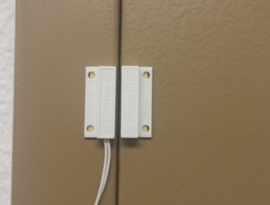
How to install the door reed switch? We generally mount half of the switch on a fixed/immovable surface and the magnetic half is installed on the movable surface. In our case, I installed the magnetic half on the door and the switch half on the wall near where the door closes. Both halves must be in the correct position and at the correct distance to make contact. Below you can see the correct positioning and installation of the door contact sensor.
|
Door contact reed switch installation
|
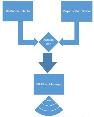
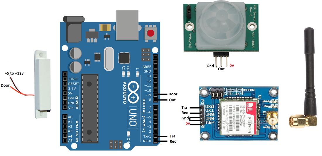
Arduino Home Security – Project Circuit Diagram
Coming to the circuit diagram of the project. Only four I/O pins of Arduino Uno are used in the project. Two pins are from the Uart channel Pin#0 and 1 of the Arduino Uno. The other two are pin no. 8 and 9. Pin no. 8 of arduino uno is connected to PIR motion sensor output pin and pin no. 9 of arduino uno is connected to door contact sensor. The Pir motion detector and door contact sensor can be powered by the +5 volt output of the Arduino. But I prefer to use an external power supply to power the pir and door sensor.
The door contact switch can be powered from +5v to +12v. I powered it with 5v power supply. If you insert +12 volts into the reed switch, you may need to insert a resistor in series with the reed switch because the Arduino pins are tolerant of 5 volts and +12v (when contact is made) may destroy the Arduino input pin . When contact is made by the reed switch, the input voltage appears on the Arduino digital pin. In our case, in Door (Pin nº 9) pin. If the voltage is above 5V, it may destroy the Arduino input pin. Therefore, be careful before turning on the reed switch.
Note: I write +12 v due to the fact that the door sensor is installed far from the main microcontroller (Arduino, in our case) and after contact the voltage drops on the wire due to the length of the wire.
GSM module needs extra power while sending SMS. Use an adopter that can supply 1 continuous Ampere of current at 5 volts to power the sim900 gsm module. The 1 amp adopter is enough to power all components (Arduino, Pir, Reed switch and Gsm module) used in the project circuit.
In the loop function two variables are declared S1 and S2 . Both variables are used to store the status of the PIR sensor and the port. The statement S1=digitalRead(door) is checking the status of the door sensor and storing the status in the variable S1. The statement S2 = digital readout (output) is checking the status of the pir and storing its status in variable S2 . Then, an if statement compares the status of both sensors/variables ( S1 and S2 ). If the PIR output is high and the contact sensor is low, control enters the body of the IF statement. In the body of the statement if NO commands are used to send a text message on a specific mobile number.
To send commands by Arduino on its Uart port Serial.println instruction is used in arduino ide. First “AT+CMGF=1” is to send. This command sets the sim900 gsm module into sms text mode. So “AT+CMGS=” is sending with “\”+923425500809\”” . In fact, it is the recipient's SIM number or the number to which we want to send the SMS. The backslash in the last instruction prevents the double quotes from being executed by the Arduino IDE. Sim900 requires the mobile number to be enclosed in double quotation marks. After the number comes the body/text of the SMS. I am sending my website name www.microcontroller-project.com as text. You can send whatever you want. Then comes the most important statement Serial.write(26) . To finalize the message and send it, sim900 requires Ctrl+Z command. If we translate Ctrl+Z into ascii code, it will be translated as '26'. So at the end of the code we are sending Ctrl+Z command to sim900 to send the text message.
Future work
The project can be updated by controlling other appliances like lights and alarms, etc., if any threats are detected. Arduino relay board containing multiple relays can be used to turn peripherals (lights, alarm) on and off. Alongside an SMS alert message, an email can also be sent to the house owner using the GPRS function of the sim900 gsm/gprs module.