In this project we are going to create a heart rate monitoring system that will be able to send readings in bpm to the doctor directly over the internet using the MQTT protocol from anywhere in the world.
The ESP 8266 and Arduino are used to read the sensor reading and then send it to the broker which is hivemqtt, from the broker the APP that stays with the doctor receives the reading and the alerts.
Technical information
The heartbeat can be measured by the infrared LED and a Photodiode, now the sensor can be connected to the Arduino or any analog pin of the microcontroller, the values can then be rectified and sent to the ESP module. From there the data is sent to the cloud.
From the cloud, the mobile application receives the readings and thus the heart rate can be monitored.
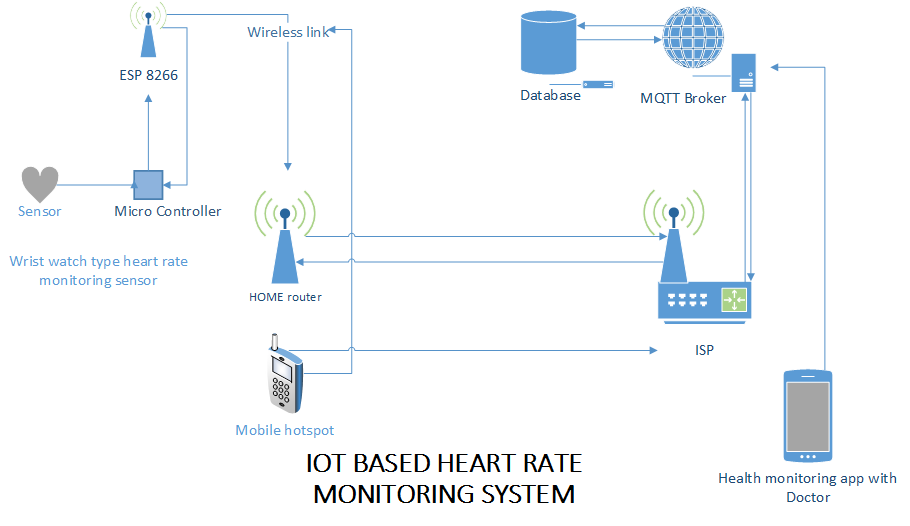
Basic system network
The heart rate monitoring system is connected to the home's WIFI router or cell phone hotspot from there the data is sent to the cloud and then the broker sends the data to the mobile application from which the doctor can monitor the changes in the heart evaluate.
As we are using MQTT there will be no need to open a port on the router or assign a specific IP to the module, all traffic passes through the MQTT protocol.

Figure 1 Basic communication block diagram
The anatomy of the complete project
The project has two parts, one to take readings and send them to the cloud called the control block, the second is the monitoring part, which has a mobile application that receives the data.
- Arduino and heart rate sensor
- Mobile App Monitoring
1. Heart rate monitoring

Figure 2 Something for system
- Block 1 Receives the analog reading from the sensor and sends block 2 for calculation in bpm.
- Block 2 always takes the sensor readings, there are certain readings in the system, which are always compared with the readings if they meet the condition the system sends an alert signal and also keeps sending the heart rates to the ESP module.
- Block 3 is publishing the readings and alert signal from block 2 in two different topics so that the doctor can set the mode between just alert and diagnosis.
2. Mobile App

Figure 3 Something for mobile APP
- Block 1 receives the analog reading from the sensor and sends block 2 for calculation in bpm. There are two modes in the app, one is always selected and is the default mode, which is alert mode, the other mode is diagnostic mode thread.
- Block 2 it receives the data from the broker which is a callback function
- Block 3 handles the display of the mobile app and controls switching between modes. If the APP is in alert mode then it notifies you when the patient is in crisis or has a problem through notifications, but in diagnostic mode the app simply subscribes to the diagnostic topic and then displays the reading on the screen.
Source code: