Circuit Summary-
-
Circuit easy to understand and assemble.
-
This circuit is used to give a visual effect when a vehicle is turning left or right.
-
If the vehicle is turning to the right, the yellow color of the LED will flash.
-
If the car turns left, the red LED will flash in this circuit.
-
This circuit is built with the help of timer IC CD4017 and IC NE555.
Principle behind the Circuit-
This is a very easy circuit that can be used in automobiles as a sequential indicator light. This circuit is constructed with the help of two ICs – a CMOS timer IC i.e. 555 timer and a decade counter IC i.e. CD4017. In this circuit, the astable mode of timer IC 555 was used to drive the counter. Other discrete components are also used in the circuit.
The moment the power supply is supplied to the circuit, the voltage at pin 2 of IC1 decreases while the output pin of IC1 i.e. * (pin?) switches to high state. Now pin 3 of IC1 supplies a positive clock pulse to pin 14 of IC2. This high pulse drives the output pins of IC2 i.e. pins 3,2,4 and 7 high. At the same time, the output pin of IC2 is in low sequence and the rate of this sequence is proportional to the firing frequency. Now the collector of transistor T1, T2, T3, T4 starts conducting, as a result of which their corresponding LEDs of this Transistor start blinking.
Point S1 in the circuit is used to select left or right direction. Therefore, if S1 is connected to the right, all LEDs connected to the right will blink. Similarly, if S1 is connected to the left, all LEDs connected to the left will blink. Capacitor C2 in the circuit is used as a bypass capacitor.
Note- Although we have chosen yellow light for turning right and red light for turning right in this circuit, you can change the LED color as per your choice.
(For demonstration purposes, we only use one LED for turning left and one for turning right.)
Components needed to build the circuit
IC
IC1NE555
IC2CD4017
Resistor
R1 47K
VR1 500K
R3 1.2K
R4 1.2K
R5 10E
Capacitor
C1 1uF
C2 220uF
LED
D1-D8 Any color
Transistor
T1 BC547
T2 BC547
T3 BC547
T4 BC547
12V power supply

Fig. 1: Prototype car indicator circuit based on 555 IC designed on a breadboard
Circuit diagrams
| Circuit Diagram-555-IC-Based Car Indicator | 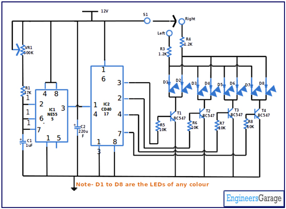 |