This tutorial is about interfacing a servo motor with the nodemcu esp8266 WiFi module. A web page is served by nodemcu that lists the servo motor controls. User can connect to nodemcu esp8266 and access web page. To open the web page in the browser, the user must enter the HTTP address of the server serving the web page. There are two types of servo motors AC and DC servo motors. AC servos run on alternating current and consume a lot of power. Lots of power means they can pick up heavier loads. AC servos are used in industrial applications. AC servos can move their axis accurately to any angular or linear position. They have a controller with a feedback mechanism that is used to adjust the control variables. DC servo motors, on the other hand, are popular in medium applications such as toys, etc. AC and DC servo motors can rotate back and forth with 360° rotation. One can easily control the speed and speed of servo motors using any commercially available servo motor controller.
Servo motor in tutorial
|
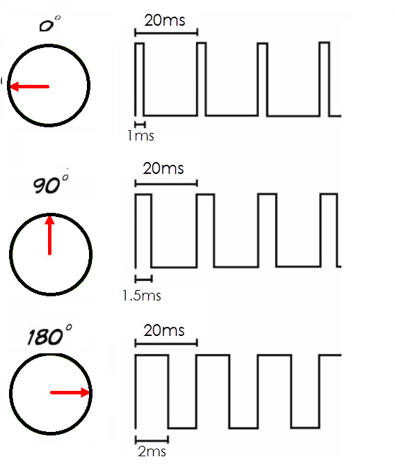
In this tutorial I will use DC servo motor. DC servo motors are popular among DIY circuit makers. They are also used in toys and are known as RC servo motors. Rc servomotors are small, cheap, and easy to use systems involving microcontrollers or chips (used in toys) dedicated to a singular purpose. RC servos can only rotate 180 degrees. Its purpose is to provide accurate localization in angular fields from 0 to 180 degrees. The Rc servo motor that I will use in the project is the tower pro micro servo sg90. The Sg90 servo motor works at 4.8 volts. The small torque produced by the SG90 at 4.8 volts can shift a load of 1.8 kg per cm. The shaft rotation of SG90 servo motor depends on the frequency of the PWM signal and the duty cycle. The Pwm frequency requirement for most RC servo motors is 50 Hz. They can rotate between 0 to 180 degrees in the pwm signal duty cycle between 1 millisecond to 2 milliseconds. The 1 millisecond duty cycle at 50 Hz frequency moves the servo axis to an angle of 0 degrees. 1.5 ms moves to 90 degrees and 2 ms to 180 degrees. You can calculate the duty cycles for other angles yourself. For example, for a shaft rotation of 45 degrees, the duty cycle will be 45/180 = 0.25, so 1 (0 degrees) + 0.25 = 1.25 ms.
|
Sg90 servo motor pwm signal requirements, duty cycle and frequency
|
Tower Pro sg90 servo motor image and pinout are given below. The Tower Pro servo motor has 3 pins. Two are power pins and the third is PWM control pin. You can connect the red wire to +5 volts. Make a black background. Connect the yellow wire to the PWM signal of the controller you are using in the project.

servo tower pro sg90
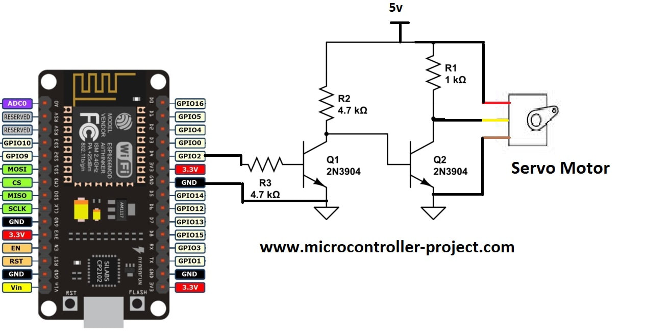
Project circuit diagram
Nodemcu esp8266 works on 3.3 volts and the servo motor requires 5 volts for its operation. Therefore, we need different power supplies for both peripherals. The Nodemcu is powered by the computer's USB port and the servo is powered by another 5 volt adopter. GPIO-2 or D4 pin of nodemcu esp8266 12e is outputting pwm signal for servo motor rotation. The Pwm signal output by the nodemcu is also in 3.3V TTL format. It must also be increased to 5v TTL before powering the servo motor. I used a pair of transistors for this purpose. The first transistor boosts the pwm signal to 5 volts, but inverts the signal. The output of the first transistor is fed to the input/base of the second transistor. The second transistor inverts the signal again and brings it back to the original source form with the TTL level raised to 5 v. Note that the ground of the nodemcu and the 5 volt power supply are grounded in common in the circuit.
Servo motor with nodemcu esp8266 WiFi module
The project code is written in Arduino IDE. Fortunately, Arduino has many libraries for each function it offers. To interface the servo with Arduino or Arduino supported boards, there is a predefined library called “Servo.h”. I included this library in my code and called its functions in code that is quite easy to use. First the 'ESP8366WiFi.h' library was imported in code. This library contains functions used to initialize the nodemcu server and start the nodemcu esp8266 WiFi. Then the 'Servo.h' library was imported. After that, enter the SSID and password of the WiFi network you want your nodemcu to be connected to. I hope you are doing this DIY project at home, in this case you will have to connect your nodemcu to your home WiFi router.
const char* ssid = “Your SSID”;
const char* password = “Your Wifi password”;
Enter the SSID and password in quotation marks. In the configuration function, the Arduino serial communication channel is opened at a baud rate of 115200 bps. After the Nodemcu PWM (Pulse Width Modulation) output pin is set. Then the nodemcu request to your WiFi for an IP assignment and the beginning of the server code instructions are recorded.
|
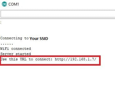
Just make the circuit and load the above code into your nodemcu WiFi module. Before uploading, make sure the correct board is selected in board management. After uploading, open the nodemcu serial monitor. As soon as you open the serial monitor, you will see nodemcu asking your router for an IP assignment. After IP assignment, nodemcu will start its server and print the server address on the serial monitor. This address is actually the address of the web page that has servo motor controls. You must enter this address in your browser. If you see nothing on the serial monitor or only arbitrary, complete characters, look for the baud rate in the serial monitor window. It should be set to 115200. Check for any possible lost connections.
|
|
Note: Both the server (nodemcu) and the client (mobile, desktop, laptop and notebook) must be connected to the same WiFi network to communicate with each other. If someone is on another network, you will not be able to load the web page in the browser.
When you get the server address from the Arduino serial monitor window like the one given above. You must enter it in your browser. If your server and client are on the same network, you will see the control page in your browser. Control page controls are provided below.
When you get the server address from the Arduino serial monitor window like the one given above. You must enter it in your browser. If your server and client are on the same network, you will see the control page in your browser. Control page controls are provided below.
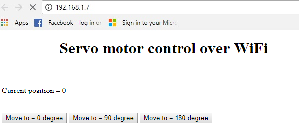
Servo motor with nodemcu esp8266 WiFi module web page control buttons
The control page shows the current status of the servo motor axis. It also contains 3 buttons. You can rotate the servo motor shaft in these three defined angles. What happens when you press the button? The loop function in the code is running continuously. Waiting for customer request. When a request arrives, it checks the contents of the request, decodes them and performs the function requested by the client (Moves the servo motor axis). Before closing the connection loop function responds to the customer the current status of the servo motor axis.
Future work
Future work
This tutorial is limited to just three angles. For the future, one could define a text box on the HTML page and take the axis rotation angle as user input and rotate the axis as entered. This can be done using HTML forms and the submit button.
Download the project code. The folder contains the Arduino project .ino file. The code is open source. You can edit and modify it according to your needs. Please provide us with your feedback on the project.
Codes/Files