
This tutorial demonstrates how to create a web server using Arduino and ESP8266 that is updated with AT Firmware. ESP8266 WiFi modules come with pre-installed AT command firmware. Before continuing with this tutorial, you can learn the basics of ESP8266 and AT commands to configure it as a web server in the following articles.
Introduction to ESP8266 and Web Server using ESP8266.
Here we will connect Arduino UNO to ESP8266 using serial communication and Arduino programming to handle AT commands.
The code handles initializing the ESP8266 in the setup function, like
-
Reset the module.
-
Configure it as an access point.
-
Prints the module's IP address.
-
Configure it as a server on port 80 and for multiple connections.
Flashing again with AT firmware:
This step can be skipped if you are new to ESP8266 and have recently purchased the module, as ESP8266 modules come with preloaded AT command firmware. If you have previously used the ESP8266 with NodeMCU firmware and LUA script, you must update with the latest AT command firmware before continuing with the tutorial.
This part of this tutorial will give you an idea about how to flash new AT firmware for ESP module. You can download the AT firmware here.
You can use USB-TTL converter to update ESP8266 with this firmware.
For detailed instructions on how to update the ESP8266, see this article. In this article you will find details on how to update the ESP8266 with NodeMCU. We will use the same software to flash AT firmware.
Connections for Flash mode:
Normal connection details are as follows:
|
Wi-Fi module |
USB-TTL
|
|
Vcc |
3.3V |
|
Gnd |
Gnd |
|
Texas |
RX |
|
RX |
Texas |
|
CH_PD |
Connected to 3.3V to enable chip firmware initialization |
Don't forget to pull CH_PD HIGH, you will not receive response from the module if this is not done.
In addition to the connections above. To enter the firmware flash mode, we need to make an additional connection, the easiest thing is to use a breadboard for this.
ESP-01 GPIO0 – Pull down connecting to GND
You can follow all the steps in this tutorial to update the ESP8266, except you must choose the Config tab and click the little gear symbol on the first one and navigate to the AT Firmware you downloaded.

Figure 1: AT Firmware Screenshot
And click the Flash button to Flash. You can check the operation by sending AT commands.
Arduino to ESP8266 via serial communication:
See how to configure Arduino to communicate with the ESP8266.
The wiring is very similar to the FTDI.
Arduino 3.3V to ESP8266 VDC
Arduino Pin 3 for ESP8266 RX
Arduino pin 2 for ESP8266 TX
Arduino GND to ESP8266 GND
You can use a simple serial input and output sketch. To check operation.
|
#include SoftwareSerial ESPserial(2, 3); //RX Texas
null configuration { Serial.begin(9600); //communication with the host computer //while (!Serial) { ; }
// Start the software serial for communication with the ESP8266 ESPserial.begin(9600);
Serial.println(“”); Serial.println(“Set NL and CR on the serial monitor.”); Serial.println(“Ready”); Serial.println(“”); }
empty loop { // listen to the ESP8266 communication and then record it on the serial monitor if (ESSerial.available ) {Serial.write(ESSerial.read ); }
// listens to user input and sends it to ESP8266 if (Serial.available ) { ESPserial.write(Serial.read ); } } |
Once everything is configured, open the serial monitor and set the baud rate to 9600, you should receive the welcome message.

Figure 2: Screenshot of the Arduino serial terminal
Arduino web server:
The web server can be created by configuring the ESP8266 as an access point and other devices can connect. See the detailed article about the web server here.
Our goal is to send all Arduino AT commands in the correct order to make the ESP8266 an AP and allow other devices to access and control it.
Here we are creating a Function in the Arduino code to send the AT commands and receive the command responses.
String sendData (String command, const int timeout, boolean debug)
String Command – will load the command to be sent.
Timeout – maximum waiting time for a response.
Debug – to know the status of the ESP8266.
When there is a data request, if the string +IPD is in the serial data, then the HTTP Responses which are HTML Codes are sent in real time to create a page with the text “HelloWorld” and a Button “LED1” which is programmed to toggle the Arduino's built-in LED. After uploading the code, open the Arduino IDE serial monitor. You can see the responses from the ESP8266 module.
Connect to the ESP8266 access point.
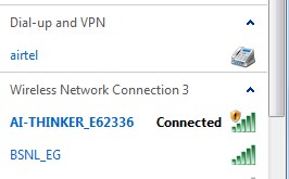
Fig. 3: Screenshot of Wi-Fi hotspots
You may see a page like this when you navigate to the IP address printed on the serial port.
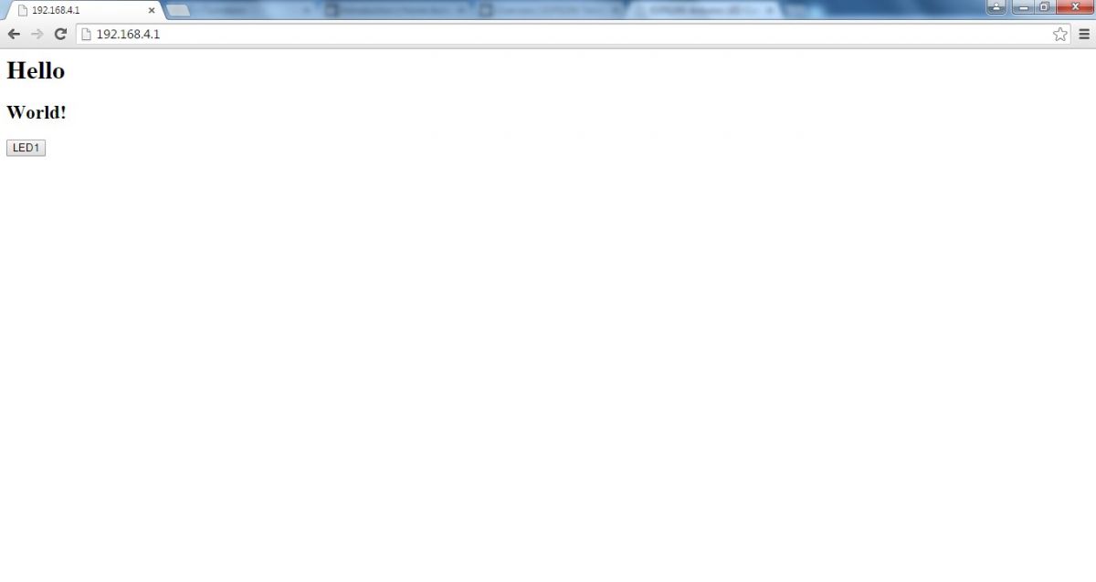
Fig. 4: Screenshot of the web page hosted by Arduino Web Server
Click the “LED1” button to toggle the built-in LED on the Arduino UNO.
You can also add buttons and control any number of pins by replicating the code.
Check this video


