
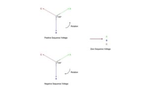
Every power system element presents an impedance to different current phase sequence components that may not be similar. For example, the impedance that a part of a device presents to positive sequence current is not the same as that to negative or zero sequence current. Therefore in unbalanced error calculations each equipment has three impedance values, one of which corresponds to each sequence current, namely:
-
Positive system impedance (Z 1 )
-
Negative sequence impedance (Z 2 )
-
Zero impedance (Z 0 )
The impedance that a circuit or device presents to positive sequence current is the system's positive impedance, and Z1 represents this . Impedances occurring in any course or device in comparison to negative sequence and zero sequence currents are also mentioned Negative sequence impedance (Z 2 ) and zero impedance (Z 0 ) .
Important points
The following points must be observed:
- In a balanced three-phase system Each part of the device or circuit offers only one impedance: that supplied to the positive or normal current. This is to be expected since there are negative and zero arrangements in the symmetric three-phase system.
- In an unbalanced three-phase system, each part of the device or circuit has three impedance values: positive sequence, negative sequence, and zero sequence impedance.
- The positive and negative impedances of linear, symmetric and static circuits. (e.g., transmission lines, cables, transformers, and fixed loads) are identical and similar to those used in balanced condition analysis. This occurs because the impedance of such circuits is independent of the phase order, as long as the applied voltages are proportional. The positive and negative sequence impedances of rotating machines (e.g. synchronous and induction motors) are generally different.
- The zero impedance of the system depends on the path that the zero current of the system takes. Because this path usually differs from the path taken by the system's positive and negative currents, the system's zero impedance is usually different from the system's positive or negative impedance.
Sequence impedance of power supply elements
The interpretation of impedances in different Power System Elements (e.g. generators, transformers, transmission lines, etc.) into positive sequence, negative sequence and zero sequence currents are of significant importance in determining the fault current in a System unbalanced three-phase . A real concern of this post on this topic is not addressed, but brief introductory explanations may be of interest here.
Below are the three main equipment required for the Sequence Impedance of Power Supply Elements.
-
Synchronous generators
-
Transformers
-
transmission lines
Synchronous generators

The positive, negative and zero impedances of these rotating machines are different. The positive impedance of a synchronous generator is equal to the synchronous impedance of the device . Zero impedance is much smaller than positive impedance. Zero impedance is a variable quantity and if its value is not specified it can be assumed that it corresponds to positive impedance. Expressed simply:
Negative system impedance
Zero impedance = variable element = may be assumed equal to positive sequence impedances if its value is not specified.
It may be useful to mention here that every impedance Z t in the earth connection of star-connected systems leads to an impedance of 3 – Z t per phase. The three equal zero currents in phase do not sum to zero at the starting point, but flow along the neutral conductor connection .
Transformers
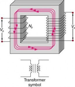
Because transformers have the same impedance when the phase rotation is reversed, their positive and negative sequence impedances are equal. This value is similar to the transformer impedance. However, the zero impedance of the system depends on grounding. When a ground current flows through the circuit, the zero sequence impedance is equal to the positive sequence impedance, or infinity.
Positive impedance
= negative sequence impedance
= transformer impedance
Zero impedance
= positive impedance of the system if a circuit for ground currents is present
= Infinite if there is no passing circuit for ground current.
transmission lines

The positive and negative sequence impedances of a line are equal, this value corresponding to the normal impedance of the line. This is assumed because the phase rotation of the currents does not cause a difference in the line constants. However, zero-sequence impedance is generally much greater than positive-sequence or negative-sequence impedance. Expressed simply:
Positive impedance
Zero impedance
Conclusion
In summary, it is critical to understand the intricacies of sequence impedance, including capacitive and inductive reactance, in single-phase and three-phase power systems. This knowledge, which includes elements such as conductors, insulators and the effects of AC and DC cycles, helps improve fault analysis, system stability and protection systems.
Understanding sequence impedance in relation to the frequency and amplitude of sine and cosine waves provides valuable information about system behavior during faults. This paves the way for advanced modeling and simulation tools that optimize system design and operations. By addressing these complexities, we unlock the future of resilient and sustainable energy systems that meet the needs of the modern world.