Why RS232?
From simple analog communication through telephone wires to typical USB cables for exchanging data, we have come a long way in the field of communication. RS232 was the first milestone achieved on this journey. It was a standard for electromechanical typewriters and modems for digital data exchange introduced in 1962 by the EIA Radio Branch. It made data exchange more reliable on the analog channel. The standard defined voltage levels that made it immune to noise disturbances and reduced error in data exchange.
As technology grew, many electronic devices were developed during this time, such as computers, printers, testing instruments, etc. There came a time when manufacturers felt the need to exchange information between these electronic devices. For example, exchanging data between a computer and a printer or two computers. But there was no standard or method to accomplish this task. RS232 was the only standard available at the time used for data exchange. So, they thought about adopting this standard in electronic devices for digital data exchange. But the standard failed to meet the requirements, as it was developed specifically for modems and teletypes. T
To overcome this problem, designers began implementing an RS232 interface compatible with their equipment. Just like an HP computer, it can only use HP peripheral devices. Because of this, the market has been flooded with different manufacturers with their own standards for their devices. This has led to common problems such as non-standard circuit pin assignments in connectors and incorrect or missing control signals. Lack of adherence to the standard has produced a thriving industry of breakout boxes, patch boxes, test equipment, books, and other aids for connecting disparate equipment. So, to end all these disparities in equipment, a union of manufacturers built a transmitter that provided +5V and -5v and labeled them as “RS-232” compatible and they are the same to this day. The standard was revised several times after the initial one and updated by the electronics industries association. The name of the standard was also changed from RS232 to EIA232. The Electronic Industries Association has published three modifications, the most recent being EIA232F introduced in 1997.
What is RS232 – “RECOMMENDED STANDARD 232”
RS-232 is a standard communication protocol for connecting computers and their peripheral devices to enable serial data exchange. In simple terms, RS232 defines the voltage of the path used to exchange data between devices. It specifies common voltage and signal level, common pin wire configuration, and minimum quantity of control signals. As mentioned above, this standard was designed with specifications for electromechanical teletypes and modem systems and did not define elements such as character encoding, character framing, error detection protocols, etc., which are essential features when data transfer occurs between a computer and a printer. Without which data transfer between a computer and a printer could not be adopted. To overcome this problem, a single integrated circuit called UART, known as universal asynchronous receiver/transmitter, is used in conjunction with RS232.
That's how the whole arrangement works.

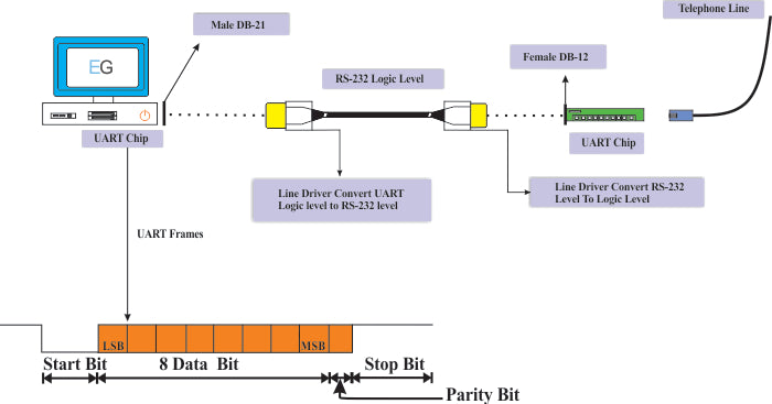
Figure 1: Diagram explaining serial data exchange between PC and device using RS232 protocol
It is clear from this figure that UART, line drivers and RS232 are three separate parts of the system, each with its own characteristic features. UART and line drivers are the parts of RS232 to improve system quality during serial data exchange.
A standard definition has been given by the EIA to define RS232 as “an interface between data terminal equipment and data communications equipment”. A typical RS232 system is shown below.

Figure 2: Image explaining a typical RS232 system
DTE- A DTE stands for data terminal equipment, it is an end instrument that converts user information into signals or reconverts the received signal. It is a station functional unit that serves as a source or sink of data and provides communication control function according to the link protocol. A male connector is used in DTE and has pinout configuration.
DCE -DCE stands for data communications equipment. It sits between the DTE and the data transmission circuit, for example, the modem. A DCE device uses a female connector that has holes in the surface to hold the male connector.
A minimum of three signals are required for communication between a DTE device and a DCE. These signals are a transmission line, a reception line, and ground. These two devices communicate via handshake. It allows a DTE and DCE device system to recognize each other before sending data.
Handshaking is a process in which a DTE device sends a signal to a DCE device to establish a connection between the devices before the actual data transfer. Defines the parameters of the communication channel established between two devices before the start of normal communication over the channel. It follows the physical establishment of the channel and precedes the normal transfer of information. Handshaking allows you to connect relatively heterogeneous systems or equipment through a communication channel without the need for human intervention to define parameters. This same concept is used in RS232 to allow two devices to communicate before the actual exchange of information.
All these terms together give a complete picture of an RS232 system starting from DTE to DCE with UART, line drivers and RS232 as conjunction between them.
Implementation and specifications
Implementation of the RS232 standard

Figure 3: Block diagram explaining the implementation of RS232 in devices
The RS-232 interface works in combination with the UART universal asynchronous receiver/transmitter. It is a piece of integrated circuit integrated inside the processor or controller. It takes bytes and transmits the individual bits sequentially in a frame. A frame is a defined structure, carrying a meaningful sequence of bits or bytes of data. It has a start bit followed by 8 data bits, a parity bit and a stop bit. After the data is transformed into bits, separate line drivers are used to convert the UART logic level to RS-232 logic. Finally, the signals are transferred along the interface cable at the specified RS-232 voltage level. Data is sent serially over RS232. Each bit is sent one after the other. T
This mode of transmission requires the receiver to be aware of when the actual data bits are arriving in order to synchronize with the incoming data. Therefore, logical 0 is sent as a leading bit. The start bit in the frame signals to the receiver that a new character is arriving. Once the receiver recognizes it, the next five to eight bits are sent, representing the character. This is followed by the parity bit used for error detection. Parity bit is used to specify an even or odd number in the set of bits. For error detection, we add an extra bit to the data word. The transmitter calculates the bit value depending on the information sent and the receiver also performs the same calculation. It checks the parity value with the calculated value. The stop bit helps the receiver identify the end of the message. The start bit always has a space value and the stop bit has a mark value. Now, if a receiver detects a different mark value when the stop bit should be present, it knows there is a synchronization error. This causes a framing error condition on the receiving UART. The device then attempts to resynchronize with newly received bits. At the other end, again, the line driver interface converts it to UART compatible logic levels. At the destination, a second UART reassembles the bits into bytes. This is how RS232 made data exchange compatible and reliable.
Standard RS232 Specifications
RS 232 is known as a complete standard . It guarantees perfect compatibility by defining not only electrical, but also functional and mechanical characteristics. For example, voltage levels, slew rate, signaling rate, pluggable connector, pin identification, etc. All specifications are summarized in this block diagram with their values and examples.

Figure 4: Block diagram summarizing RS232 standard specifications
This section deals with the detailed understanding of each characteristic of the standard.
Electrical Characteristics
Includes specifications on voltage levels; rate of change and level of voltage resistance. RS232 pinout signals are represented by voltage levels relative to common. It specifies the maximum circuit voltage as 25v. On the transmitter side, the driver output specifies voltage +3v to +15v for high level and -3v to -15v for low level. Similarly for receiver output put high level so voltage is +3v to +15v and low level voltage is -3v to -15v. It should be known that the receiver logic provides +2v noise margin. The dead area between +3v and -3v is designed to absorb line noise. In RS232 specification low level -3v to -15v is defined as logic '1' is in ON state and referred to as 'Marking' while high level +3v to +15v is defined as logic '0' is in OFF state and known as 'Spacing'. The RS232 standard also limits the maximum slew rate, which reduces interference between the two signals. Slew rate is defined as the rate of change of the output voltage with respect to time. The maximum slew rate allowed in RS232 is 30 V/microseconds, which slows the rise and fall times and reduces interference. Circuits driving an RS-232 compatible interface must be capable of withstanding an indefinite short circuit to ground or any voltage level up to 25 volts. Some computer equipment ignores the negative level and accepts a zero voltage level as the OFF state. The output signal level generally ranges between +12V and -12V.
RS232 Logic Specification Figure

Figure 5: Graph showing electrical characteristics in RS232
Mechanical characteristics
This area concerns the mechanical interface.
A standard 25-pin connector was used initially. It specified the minimum connector size that can accommodate all signals. Each pin has been pre-defined to allow compatibility between host and peripheral systems . Data terminal equipment uses male connector and data communication equipment uses female connector pins. Another important concept related to the connector is the gender type. In the electrical and mechanical trade, each connector comes in pairs. One is a male connector and the other is a female. Male connectors have protruding pins on the surface, while female connectors have holes to hold the male connector. Also in RS232, DTE has male D-25 connectors, while DCE has female D-25 connectors. A combination of D-SUB 25 MALE and D-SUB 25 FEMALE connector is used to connect a DTE and DCE specifying common voltage and signal level, common pin wire configuration and minimum amount of control signals.

Fig. 6: Images of the D-SUB 25 MALE connector in RS232-based systems
A 25-position connector was widely used, but nowadays a 9-pin connector is used in many applications. It is sufficient in most circumstances, as many of the lines available on the 25-pin RS232 connector are rarely used. The 9-way connector is capable of providing all the connectivity required for most applications and allows the application to transmit and receive the necessary signals as per the requirements.
A 25-pin connector and a 9-pin connector are shown below.

Figure 7: Pin numbers on 25-pin and 9-pin connectors
Specifications cont.
Functional features
This is the third area that concerns the RS232 specification. It defines the functions of the different signals that are used in the interface. These signals are defined in four categories: data, common, control and timing. There are few terms used in the table such as loop back, off or on hook and side channels.
Loop back – It is a method for carrying out transmission testing of lines at the switching center. Loop back allows the user to test their own network to ensure it is working correctly.
Off Hook – A condition that occurs when a telephone or other user instrument is in use while dialing or communicating. It was originally referred to telephones that have a separate earpiece (receiver) that hangs from the switch hook until the user wants to use it.
Secondary Channel – These are the data channels and have the same capacity as the first. For example Secondary data transmitted (STD), secondary data received (SRD), secondary request to send (SRTS), secondary release to send (SCTS) and secondary carrier detection (SDCD).
The table below shows the different signals and their functions


Figure 8: Table summarizing the RS232 pinout description
As we can see, the pattern provides many control signals. There are only some applications that require all signals defined, otherwise only a few signals are used, such as a typical modem uses only eight signals, some may require only four, two for data and two for handshake and while others may only use signal signals. data and no handshake.
Handshake and conclusion
HANDSHAKE
The RS232 handshake is commonly known as the “RTS/CTS” handshake. The data terminal equipment activates the RTS pin to indicate a desire to transmit to the DCE and then the DCE responds via the CTS pin to grant permission. Henceforth, modems deactivate their transmitters when they are not needed and must transmit a synchronization signal to the receiver when they are reactivated again. In the latest version of the RS232 E standard, handshaking is redefined where CTS (clear to send) is no longer a response to RTS, but indicates permission from DCE to DTE devices. Similarly, the RTS indicates permission from the DTE for the DCE to send data. RTS and CTS are controlled by DTE and DCE and independent of each other. A detailed handshaking system with eight signal lines is explained.

Figure 9: Block diagram showing details of the RS232 handshake system
When data carrier detection is off, it indicates to the local terminal that the remote DTE has not activated its RTS and the local terminal can gain control over the line. When this circuit is on locally, it indicates to the local terminal that the remote modem has received an RTS ON condition from its terminal and that the remote DTE is in control of the carrier line. RXD means receive data from modem for DTE. TXD transmits data from the DTE to the modem. The DTR data terminal readiness pin is generally enabled when the terminal is ready to establish a communication channel through its modem. But when the DTR does not wish to accept calls from the remote terminal the circuit is disconnected. Both modems turn on the Data Set Ready circuit when the communication path is established between two locations. Now, when the terminal is ready to transmit, it turns on the Request to Send circuit, indicating to the local modem that it is ready to send data. This request is passed to the remote modem. The RTS controls the direction of data transmission. Once the terminal is ready to transmit the local modem switches on the CTS circuit to indicate that it is ready to receive data from the DTE. He also gains control over the phone line. Then, when the modem receives the call, the Ring Indicator turns on/off telling the DTE that a call is coming in to indicate that the remote modem is requesting to dial. This is a simple handshake system with eight signal lines.
Conclusion
RS232 has become the standard feature of a personal computer for connections to modems, printers, mice, data storage, and other peripheral devices. Although there are many new developments, RS232 still finds its application. The first and most important reason is the simplicity of the pattern. Allows the user to communicate directly with serial ports. There are areas such as laboratory, automation and surveying that have sustained the demand for RS232 due to the use of very expensive but old equipment. It is much cheaper to use RS232 than to replace equipment. Not only the old equipment, but also the modern automation devices such as servo drivers, CNC equipment, etc. are programmable via RS232. Toshiba has also reintroduced the DE-9M connector to the laptop. Serial ports with RS-232 are used to communicate with headless systems, such as a server where no keyboard is installed during boot. Some embedded systems use the RS232 serial port for communication as an alternative mode of network monitoring.