Just as robots that follow lines are fun, making a robot that follows walls is even more exciting. A wall-following robot is designed to move along a wall without hitting it. It has body-mounted obstacle detection sensors that detect walls and drive DC motors attached to the wheels so that the robot continues moving along the wall.
The robot can be designed oriented to the right or left or can be designed to follow either side. A right or left oriented wall follower can be designed easily with the help of just two sensors. Although more sensors can be used in manufacturing such a robot, which will ultimately improve the accuracy of the robot's path. To make a wall follower that can be sideways in any direction, at least three sensors are required and the program logic is a bit complex and sophisticated. If a right-oriented wall follower is designed, the obstacle detection sensors need to be mounted on the front and right side of the robot. If a left-oriented wall follower is designed, the obstacle detection sensors need to be mounted on the front and left side of the robot. If the robot is designed to follow either side, obstacle detection sensors must be mounted on the front, left and right of the robot. In this project, a left side wall is designed following the robot.

Fig. 1: Wall-Following Robot Prototype
The obstacle detection sensor used in a wall follower can be an IR sensor or an ultrasonic sensor. IR sensors can be used to detect a pre-determined and calibrated distance from the wall and thus, by using IR sensors, the robot is designed to maintain a fixed distance from the wall. In this case, high path accuracy cannot be achieved. Secondly, in the presence of sunlight or reflection from a black spot on the wall, the robot may not function as desired due to the limitations of the IR sensor in these cases. Although if the ultrasonic sensor is used as an obstacle detector, the robot can be designed to maintain a distance with the wall, which not only improves the flexibility of the path but also improves its accuracy. Since ultrasonic sensors operate based on the reflection of ultrasonic (sound) waves, they can be used in environments where there is sunlight or black obstacles in the way. Considering these advantages of ultrasonic sensors over IR sensors, ultrasonic sensors are used for obstacle or wall detection in this project.
The microcontroller board that provides intelligence to the robot is the Arduino Pro Mini. The robot can also be designed on any other microcontroller board. The program code developed for this robot is also compatible with Arduino UNO and will work well if the sensors and motor driver IC are interfaced in the same way as the program operates. Arduino Pro Mini is used due to its small size and light weight. Also, Pro Mini has enough GPIO pins which are required to make this robot. The program code is written and recorded using Arduino IDE.
Required components –

Figure 2: List of components required for the wall following robot
Block diagram –

Figure 3: Block diagram of the wall following robot
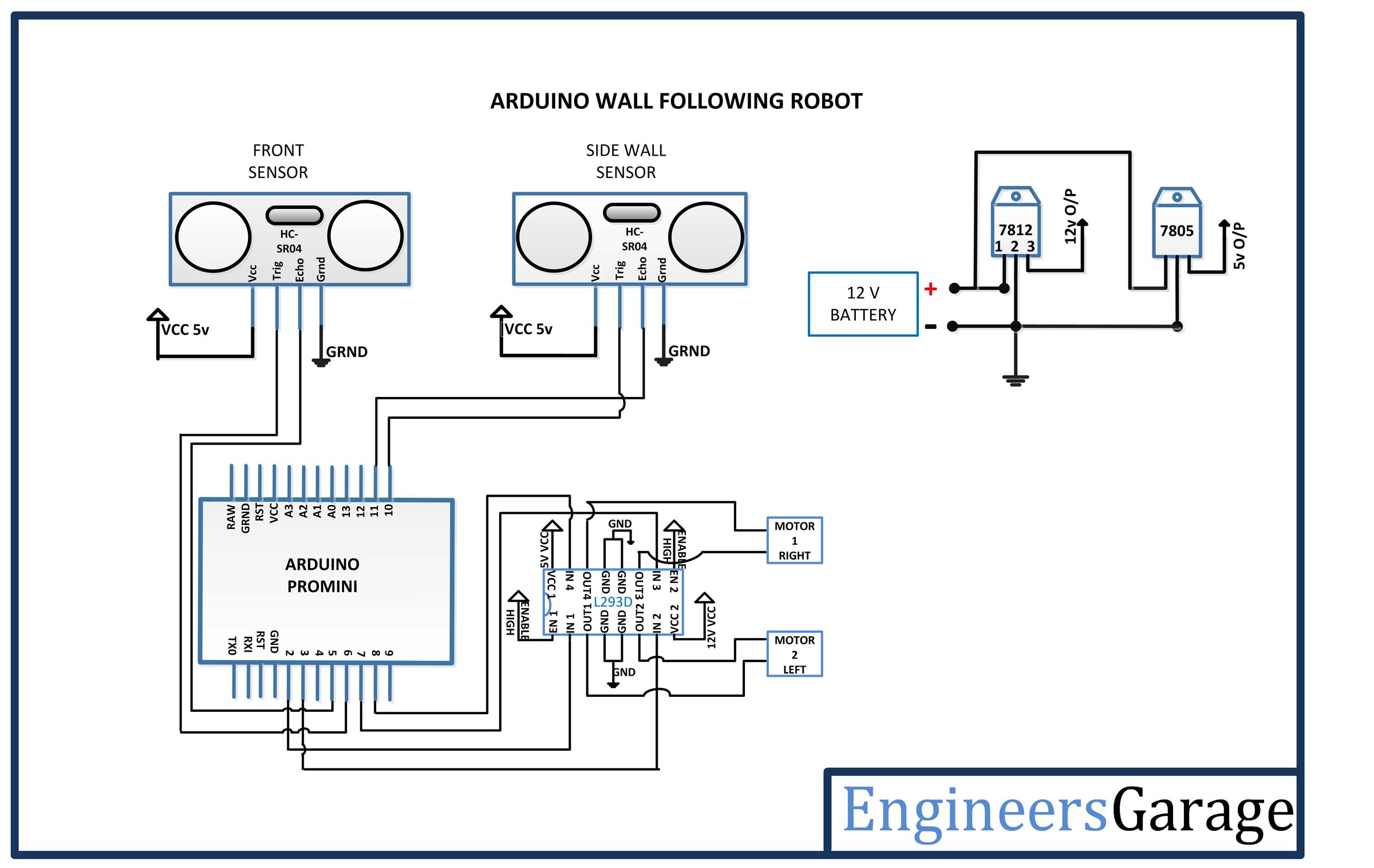
Circuit Connections –
This wall-following robot is built around the Arduino Pro Mini. The ultrasonic sensors and L293D motor driver IC interface with the controller board to make it a functional robot.

Fig. 4: Image of the electronic circuit mounted on the wall-following robot
The electronic circuit mounted on the robot and controlling its movement can be detailed in the following sections –
Power supply – In the circuit, the Arduino Pro Mini and the ultrasonic sensors need a regulated 5V DC for their operation, while the motor driver IC needs 12V DC. A 12V NIMH battery is used as the primary power source. The battery power is regulated to 5V and 12V using 7805 and 7812 ICs. Pin 1 of both voltage regulator ICs is connected to the battery anode and pin 2 of both ICs is connected to ground. The respective voltage outputs are taken from pin 3 of the respective voltage regulator ICs. An LED along with a 10K Ω pull-up resistor is also connected between the common ground and the output pin to get a visual cue of power continuity. Despite using a 12V battery, the 7812 is used to provide a regulated and stable power supply to the motor driver IC.
Arduino Pro Mini – Arduino Pro Mini is a microcontroller board based on Atmega 168. It has 14 GPIO pins, 6 analog inputs, 6 PWM pins, 2 external interrupts and integrated UART, SPI and I2C. The board is just 1.3 inches by 0.7 inches in size, six times smaller than the Arduino UNO. With these features in a small size, this board is ideal for any robotics project. In this project, 8 input and output pins of the Pro Mini are used, four pins for interfacing with ultrasonic sensors and four pins for interfacing with the motor driver IC.
HC-SR04 Ultrasonic Sensor – The HC-SR04 ultrasonic sensor uses sonar to determine the distance to an object, much like bats or dolphins do. Provides excellent non-contact range detection with high accuracy and stable readings in the range of 2cm to 400cm.
There are two ultrasonic sensors used in the circuit, one mounted on the front of the robot and another mounted on the left side of the robot. The front-mounted ultrasonic sensor is connected to pins 5 and 6 of the Arduino board and the left-side mounted sensor is connected to pins 10 and 11 of the Arduino board. The ultrasonic sensor has four pins – Ground (Pin 1), Eco (Pin 2), Trigger (Pin 3) and Trigger. The VCC and ground pins are connected to common VCC and ground respectively. The Echo pins of the front and left sensor are connected to pins 5 and 11 of the Arduino board respectively, while the trigger pins of the front and left sensors are connected to pins 6 and 10 of the Arduino board.
The ultrasonic sensor works on the principle of sound wave echo. When a 10 μs HIGH pulse is passed to the trigger pin of the sensor, it transmits eight 40 KHz waves of HIGH sonic pulse triggers consecutively. A high pulse signal comes out of the echo pin as the ultrasonic wave is transmitted. This wave, when colliding with an obstacle, is reflected back and detected by the sensor. When detecting the wave again, the high pulse signal from the sensor's echo pin is terminated. The signal received from the echo pin is analog in nature. The distance to the obstacle can be measured by measuring the maximum echo pin time. This is the time between transmission and reflection of the sound wave. The distance is given by the formulas –
Test distance = (high level time × speed of sound (340M/S)) / 2
The time multiplied by the speed is divided by 2, as the time required for the sonic wave to reach the obstacle and return. Therefore, the distance measurement in cm can be given by the formulas –
Test distance = (high level time × speed of sound (340M/S)) / 2
= (high level time (microsecond) × speed of sound (340M/S)) / 2
= high level time x 340/2000000 m
= high level time x 34,000/2,000,000 cm
= high level time x 34/2000 cm
Ultrasonic sensors emit the high pulse from its pin 2, which is detected on pins 5 and 11 of the Arduino board. The program code measures the pulse durations and digitizes them into distance values using the formulas stated above. These distance values are used to maintain a defined distance with the left side wall and avoid an obstacle in front of the robot from a predefined distance. The motors are driven to maintain a predetermined distance from the left side wall.
L293D DC Motor Driver IC – The L293D is a dual H-bridge motor driver integrated circuit (IC). Motor drivers act as current amplifiers in that they receive a low current control signal and supply a higher current signal. This higher current signal is used to drive the motors. It has 16 pins with the following pin configuration:

Fig. 5: Table listing the pin configuration of the L293D motor driver IC
There are two DC motors used to make the robotic car. DC motors interface between pins 3 and 6 and pins 14 and 11 of the motor driver IC.
IC L293D controls DC motors according to the following truth tables:

Fig. 6: Truth table of L293D motor driver IC

Fig. 7: Truth table of L293D motor driver IC
Pins 4, 5, 13 and 12 of the L293D are grounded while pins 1, 16 and 9 are connected to 5 VDC and pin 8 is connected to 12 VDC. Pins 15, 2, 7 and 10 of the motor driver IC are connected to pins 8, 2, 3 and 7 of the Arduino board. The DC motor connected to the right wheel is connected to pins 11 and 14, while the motor connected to the left wheel is connected to pins 3 and 6 of the Arduino.
Geared DC Motors – In this robot, 12V geared DC motors are attached to the wheels. Geared DC motors are available with a wide range of RPM and Torque, which allows a robot to move based on the control signal it receives from the motor driver IC.
How the circuit works –
When the robot is turned on, it is initialized to move forward and continue turning left until it reaches a minimum distance with the left wall. For this, the robot is made to start moving forward and start reading the values from the ultrasonic sensors. The robot also continues to rotate to the left by turning the right side DC motor faster until the left sensor reading approaches the minimum value. From now on, the robot may face two conditions – either some obstacle appears in front of the robot or the distance with the wall may decrease due to the structure or layout of the wall. If an obstacle is detected in front of the robot at a predefined distance, the robot will turn to the right until it overcomes the obstacle. If there is no obstacle in front of the robot, the robot will continue moving forward. If the distance between the left wall and the robot is reduced below the minimum value, the robot will be moved again in the right direction by activating the motor on the left side more quickly until the distance reaches a maximum value. Arduino implements the same algorithm. This algorithm is summarized in the following flowchart –

Fig. 8: Arduino code flowchart used for wall following robot
The Arduino sketch moves the robot according to the following table –

Fig. 9: Logic Table of the Wall Follower Robot
Follow-up actions can be implemented by triggering the engines as follows –

Fig. 10: Table summarizing the Action Plan for the Wall-Following Robot
The robot can be moved forward, backward, left or right by implementing the following input logic on the motor driver pins –

Fig. 11: L293D motor driver IC logic table for wall follower robot
To slow down or speed up specific robotic movements, PWM can be applied to the input pins of the L293D driver. Thus, the ultrasonic sensors detect the distance to the wall or obstacle and the DC motors are activated to respond to the change in situation. This is how the robot moves by following the wall and overcoming any obstacles.
In a right-oriented wall follower, the algorithm will be almost similar except that the robot will be designed to follow the right wall and rotate according to different situations. Designing a robot following any of the walls can be a bit complex as it will face new situations and have to decide which wall should be followed in certain circumstances.

Fig. 12: Image of Arduino-based wall following robot
Check out the program code to see how the algorithm is implemented in the Arduino sketch. Check out how the Arduino reads data from the ultrasonic sensors, compares the readings with the minimum and maximum displacements and changes the engine rotation in response to perceived situations.
Programming guide –
The code uses the new ping library for the ultrasonic sensor. Learn more about the Arduino.CC ping library and download NewPing.h.
#include
The #define directive is used to declare some constant values that will be assigned to the variables used in the code. These constants indicate how many ultrasonic sensors are used, the maximum distance the sensor should respond, and the ping interval is the time between pings from two sensors in milliseconds.
#define SONAR_NUM 2
#define MAX_DISTANCE 500
#define PING_INTERVAL 33
The following #define directives are used to determine the Arduino pin numbers used to connect the ultrasonic sensor (trigger pin and echo pin) and the pins that should be connected to the motor driver IC.
#define trigPin1 5
#define echoPin1 6
#define trigPin2 10
#define echoPin2 11
#define LM1 2
#define LM23
#define RM1 7
#define RM2 8
The following block describes the sensor object that defines the two sensors in the array. It instantiates the NewPing library object that describes the trigger pin and echo pins connected to the Arduino and the maximum distance they should measure.
New sonar Ping (SONAR_NUM) = {
NewPing(trigPin1, echoPin1, MAX_DISTANCE),
NewPing(trigPin2, echoPin2, MAX_DISTANCE)
};
The following block describes the setup function, which is used to set baud rates and defines whether the Arduino pin should be used as a digital input or output. It is used to set the baud rate for serial communication between Arduino and PC.
Serial.begin(9600);
int i;
The following instructions use the PinMode function to declare the pins connected to the Arduino motor driver as digital output.
pinMode(LM1, OUTPUT);
pinMode(LM2, OUTPUT);
pinMode(RM1, OUTPUT);
pinMode(RM2, OUTPUT);
The following instructions use the PinMode function to declare the trigger pins as output and the echo pins as input relative to the Arduino board.
pinMode(trigPin1, OUTPUT);
pinMode(echoPin1, INPUT);
digitalWrite(trigPin1, LOW);
pinMode(trigPin2, OUTPUT);
pinMode(echoPin2, INPUT);
digitalWrite(trigPin2, LOW);
The following code block initializes the range of values that the Arduino should signal to the motor driver to turn right or left or go straight depending on the distance measured by the ultrasonic sensor.
int toCloseWall = 1000;
int for FarWall = 1500;
int toCloseFront = 1000;
The main operation in the code is implemented by a decision-making loop that is called in the main function. It should be noted that in the source code, the serial.print functions are used to check the range of ultrasonic sensors during code debugging and calibration. The main function calls the readRangeFront function to measure the distance detected by the front ultrasonic sensor.
rangeFront = readRangeFront ;
It calls the readRangeWall function to measure the distance between the wall the robot is moving through.
rangeWall = readRangeWall ;
The following if condition is used to check the distance between the front sensor and the object, if the object is closer according to a predetermined range, it calls the function drive_backward, drive_forward and turn_left with some delay in between.
if (rangeFront
{
delay(500);
drive_backward;
delay(500);
delay(800);
move on;
Turn left ;
delay(1000);
go to Main;
}
The following condition is used to check the distance between the front sensor and the front wall and the side wall sensor and the side wall. If the distance measured by the two sensors is in the desired range, it calls the drive_forward function.
if(rangeWall > toCloseWall && rangeWall < toFarWall)
{
move on;
go to Main;
}
The following conditions are used to check the distance between the sidewall and the sensor and check the closest and farthest value. If the distance becomes close, it calls the drive_left function and the drive_forward function and if the distance becomes far, it calls the drive_right function and the drive_forward function.
if (rangeWall
{
delay(100);
Turn left ;
delay(100);
move on;
go to Main;
}
if (rangeWall > toFarWall)
{
delay(100);
Turn right ;
delay(100);
move on;
go to Main;
}
Goto statements are used to run the loop continuously. Check out the complete project code and save it to an Arduino to make the robot work. This completes the Arduino sketch for the wall-following robot (left side).
Project source code
###
//Program to
#include
#define SONAR_NUM 2 //defines the number of ultrasonic sensors used
#define MAX_DISTANCE 800 //Maximum distance between the object and the robot
#define PING_INTERVAL 33
#define trigPin1 6 // define pin connections for sensor and motor
#define echoPin1 5
#define trigPin2 11
#define echoPin2 10
#define LM1 2
#define LM23
#define RM1 7
#define RM2 8
int rangeFront = 0;
int rangeWall = 0;
Sonar NewPing(SONAR_NUM) = { // Define a Newping array to measure distance
NewPing(trigPin1, echoPin1, MAX_DISTANCE),
NewPing(trigPin2, echoPin2, MAX_DISTANCE)
};
void setup // configuration function to configure the pin to define whether it is input or output
{
Serial.begin(9600);
int i;
pinMode(LM1, OUTPUT);
pinMode(LM2, OUTPUT);
pinMode(RM1, OUTPUT);
pinMode(RM2, OUTPUT);
pinMode(en1, OUTPUT);
pinMode(pt2, OUTPUT);
pinMode(trigPin1, OUTPUT);
pinMode(echoPin1, INPUT);
digitalWrite(trigPin1, LOW);
pinMode(trigPin2, OUTPUT);
pinMode(echoPin2, INPUT);
digitalWrite(trigPin2, LOW);
}
int toCloseWall = 1800; //Initialize and define the values of the distance between the wall and the robot
int for FarWall = 2500;
int toCloseFront = 1000;
empty loop
{
Main:
rangeFront = readRangeFront ; // Read the sensor value by calling the function
Serial.print(rangeFront);
Serial.print("Front");
Serial.println;
rangeWall = readRangeWall ;
Serial.print(rangeWall);
Serial.print("Wall");
Serial.println;
if (rangeFront <= 400) //As the sensor value reads the small values, we are manipulating to high values
{
rangeFront = 3000;
}
if(intervalWall <= 400)
{
wallrange = 3000;
}
if (rangeFront < toCloseFront) //Condition to check if the front sensor is close to the robot
{
delay(500);
drive_backward;
delay(500);
Serial.print("Back");
//Turn right ;
Serial.print("Turn right");
Serial.println;
delay(800);
move on;
Turn left ;
delay(1700);
go to Main;
}
if(rangeWall > toCloseWall && rangeWall < toFarWall) //condition to check if the distance measured by the front and side sensor is maintained correctly
{
move on;
Serial.print("Next");
Serial.println;
go to Main;
}
if (rangeWall < toCloseWall) //condition to check if the side wall is close to the robot
{
delay(100);
//Turn left ;
Turn right ;
delay(500);
Serial.print("Turn Left");
move on;
Serial.print("Next");
Serial.println;
go to Main;
}
if (rangeWall > toFarWall) //condition to check if the robot is far from the side wall
{
delay(100);
//Turn right ;
Turn left ;
Serial.print("Turn right");
delay(500);
move on;
Serial.print("Next");
Serial.println;
go to Main;
}
}
void motor_stop // function to stop the robot
{
digitalWrite(LM1, DOWN);
digitalWrite(LM2, DOWN);
digitalWrite(RM1, LOW);
digitalWrite(RM2, LOW);
}
void drive_forward // function to drive the robot forward
{
digitalWrite(LM1, HIGH);
digitalWrite(LM2, DOWN);
digitalWrite(RM1, HIGH);
digitalWrite(RM2, LOW);
}
void drive_backward // function to drive the robot backwards
{
digitalWrite(LM1, DOWN);
digitalWrite(LM2, HIGH);
digitalWrite(RM1, LOW);
digitalWrite(RM2, HIGH);
}
void turn_left // function to turn the robot left
{
digitalWrite(LM1, HIGH);
digitalWrite(LM2, DOWN);
digitalWrite(RM1, LOW);
digitalWrite(RM2, LOW);
}
void turn_right //function to turn the robot to the right
{
digitalWrite(LM1, DOWN);
digitalWrite(LM2, DOWN);
digitalWrite(RM1, HIGH);
digitalWrite(RM2, LOW);
}
int readRangeFront //function to read the front sensor value
{
delay(50);
unsigned rangeFront = sonar(0).ping ;
sonar(0).timer_stop ;
return rangeFront;
}
int readRangeWall // function to read the left sensor value
{
delay(50);
unsigned rangeWall = sonar(1).ping ;
sonar(1).timer_stop ;
return rangeWall;
}
###
Circuit diagrams
| Circuit Diagram-Arduino-Wall Follower-Robot |
 |
Project video