The Android phone that stays in your hand most of the time is useful in many other applications besides Whatsapp, Facebook; home appliances; and monitor your health parameters. What if he could control a robot to help with his daily work? Yes, it is possible! With this project you can make a robot that can be controlled by an Android phone, through Bluetooth communication.

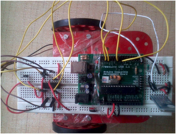
Figure 1: Arduino robot prototype operated by mobile devices
The robot is built around Arduino interfaced with a Bluetooth receiver to receive commands from the Android phone.
The basic block diagram of the system is as follows:

Figure 2: Block diagram of the Arduino robot operated by mobile devices
Bluetooth Communication
Bluetooth is a wireless technology standard for exchanging data over short distances (using short-wavelength UHF radio waves in the 2.4 to 2.485 GHz ISM band) from fixed and mobile devices and building personal area networks ( PANs). Invented by telecommunications provider Ericsson in 1994, it was originally conceived as a wireless alternative to RS-232 data cables. It can connect multiple devices, overcoming synchronization problems.
The HC-05 module is an easy-to-use Bluetooth SPP (Serial Port Protocol) module designed for transparent wireless serial connection configuration. HC-05 is a 6-pin module. The module has 6 labeled pins on the back, but most modules only have 4 of them filled with pogo pins. KEY & STATE appear not to be necessary as KEY is used to update the device and STATE simply indicates whether the device is active or not. So that leaves just GND, VCC, TXD, RXD.

Figure 3: Image of the HC-05 Bluetooth Module
To connect the Module to Arduino, we need to use the Serial pins (Tx and Rx) provided on the board.
Connections with HC-04
Making connections with HC-05:
Some modules have VCC labeling for working voltages up to ~6 volts and DO NOT like anything but 3.3 volts on the VCC line. We must use a level converter for 3.3V on the RXD line. Use two resistors as a simple voltage divider to convert the TTL level. A 2.2k ohm resistor to ground, connected to a 1k ohm resistor, to the TXD line on the MCU.Connect the module's RXD pin to the Arduino's TXD (Digital Pin 1), using the voltage divider configuration shown below:

Figure 4: Arduino and HC-05 Bluetooth module interface circuit diagram
Now connect the TXD of the module to the RXD of the Arduino (Digital Pin 0).
Android application to control robot
There are many apps on the Play Store for controlling Arduino via Bluetooth that are available for free. To keep the code simple, we will use the “Arduino Bluetooth Terminal”. Download and install the same and pair the Bluetooth receiver with your cell phone. A screenshot of the app is provided below:
Figure 5:
Screenshot of the Android app showing the Bluetooth connection to the robot

Figure 6: Screenshot of the Android application showing messages sent to the Arduino robot
Robot motor and assembly interface
The motors are interconnected through the Motor Driver (Dual H-Bridge type), the commonly used version is L293D, which is available in 18-pin DIP.
Figure 7: L293D Motor Driver IC Pin Diagram
The robot assembly can be shown below:

Figure 8: Image showing the mechanical design of the Arduino Robot
The Android mobile app to control the robot is available for free on the Play Store.
The motor driver inputs are connected to Arduino pins 5; 6; 7 and 8 respectively.

Figure 9: Image showing chassis and body of the Arduino Robot

Figure 10: Image of the Arduino robot controlled by the Android phone
Project source code
 ###


 // Android Phone Controlled Robot
 // Successfully Tested on Android App --> 'Arduino Bluetooth
 // Terminal '; it is available free on the Google Play Store
 int state;
 int flag=0;
 void stp ;
 void fwd ;
 void left ;
 void right ;
 voidback;
 void setup
 {
 pinMode(7,OUTPUT);
pinMode(8,OUTPUT);
 pinMode(5,OUTPUT);
 pinMode(6,OUTPUT);
 Serial.begin(9600); // Baud rate set to 9600bps
 }
 void loop {
 if(Serial.available > 0) // Ckeck for command received
 {
 state = Serial.read;
 Serial.println(state);
 flag=0;
 }
 if (state == '1') // Checking Command from User
 {
 stp;
 if(flag == 0){
 Serial.println("Stop");
 flag=1;
 }
 }
 else if (state == '2')
 {
 fwd ;
 if(flag == 0)
 {
 Serial.println("Forward");
 flag=1;
 }
 }
 else if (state == '3')
 {
 back;
 if(flag == 0)
 {
 Serial.println("Backward");
 flag=1;
 }
 }
 else if (state == '4')
 {
 left ;
 if(flag == 0)
 {
 Serial.println("Left");
 flag=1;
 }
 }
 else if (state == '5')
 {
 right;
 if(flag == 0)
{
 Serial.println("Right");
 flag=1;
 }
 }
 } //loop ends here
 void fwd // Forward
 {
 digitalWrite(7,HIGH);
 digitalWrite(5,HIGH);
 digitalWrite(6,LOW);
 digitalWrite(8,LOW);
 }
 void back // Backwards
 {
 digitalWrite(8,HIGH);
 digitalWrite(6,HIGH);
 digitalWrite(7,LOW);
 digitalWrite(5,LOW);
 }
 void left //LEFT
 {
 digitalWrite(7,HIGH);
 digitalWrite(5,LOW);
 digitalWrite(8,LOW);
 digitalWrite(6,LOW);
 }
 void right // Right
 {
 digitalWrite(7,LOW);
 digitalWrite(5,HIGH);
 digitalWrite(8,LOW);
 digitalWrite(6,LOW);
 }
 void stp // Robot STops
 {
 digitalWrite(7,LOW);
 digitalWrite(8,LOW);
 digitalWrite(5,LOW);
 digitalWrite(6,LOW);
 }

 ###
Circuit diagrams
| Circuit Diagram-L293D-Motor-Driver-Arduino-Robot |  |
| Circuit-Diagram-Controller-Circuit-Arduino-Robot | 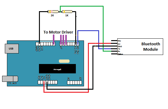 |