Requirements:
- DTMF decoder
- 3.5mm audio cable (to connect the cell phone to the DTMF module)
- AT89S52
- 7805
- Geared DC Motors
- Battery (10-12v)
- 11.0592 MHz Crystal
- L293D IC (motor driver)
- Wheel for engines
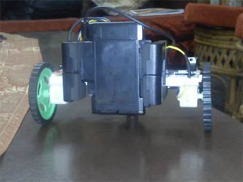
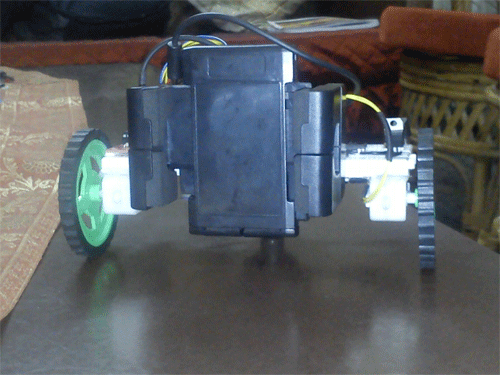
Fig. 1: Image showing the back of the 8051 microcontroller-based mobile operated robot
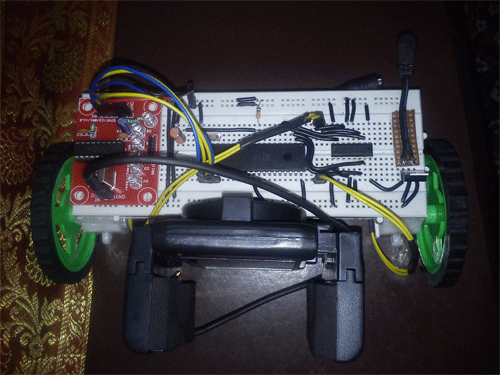
Fig. 2: Image showing top view of 8051 microcontroller based mobile operated robot
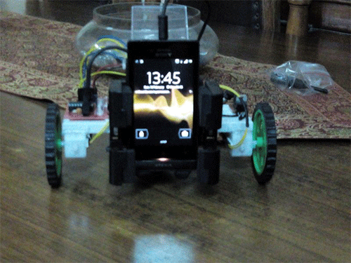
Fig. 3: Image showing the front part of the 8051 microcontroller-based mobile operated robot
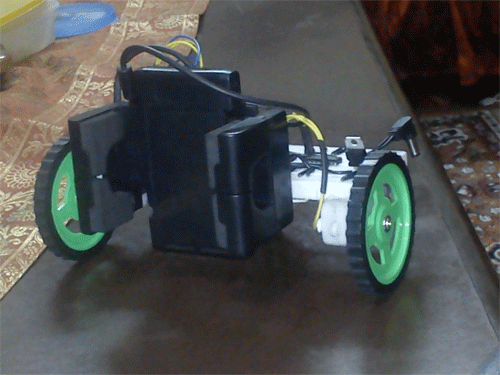
Fig. 4: Image showing side view of 8051 microcontroller based mobile operated robot
Description:
Mobile control is mainly done with DTMF decoder. DTMF stands for Dual Tone Multi Frequency. This module can receive up to 4 bits of data at a time (i.e. 0-15 decimal values).
DTMF needs two mobile platforms, one to send instructions and another to receive them.
This module contains an IC that decodes the received signals and converts them into 4-bit data.
When you press the buttons on the keyboard, a connection is made that generates two tones at the same time.

Fig. 5: Image showing DTMF frequency key mapping for a numeric keypad
generate the 1336 Hz and 697 Hz tones. Of course, the 697 tone is the same for both digits, but two tones are needed so that when you press digit 1 on the keyboard, you generate the 1209 Hz and 697 Hz tones. Pressing the digit 2 will
make a digit and the decoding equipment knows the difference between the 1209 Hz that would complete the digit
1 and 1336 Hz that completes digit 2.
This table shows the 4-bit (bit-for-bit) data output of the DTMF decoder module according to the button pressed:

Fig. 6: Table listing frequencies and respective digital outputs used in DTMF
In this project I only used 5 keys; they are:
2 ( for forward movement)
4 ( to move left) 5 (to stop the bot) 6 ( to move right)
8 (for backward movement)
A specific DTMF module consists of signal pins (mobile phone input signals via 3.5mm jack), 4 pins (D0, D1, D2, D3) for 4-bit data transmission, and a DV pin which goes high at each successful data decode.
In this project my 4-bit DTMF pins are connected to PORT2 of the MC (1.e. pin P2^0, 1, 2, 3).
L293D inputs are connected to P1^1,2,3,4 pins respectively.
L293D will help us drive DC gearmotors perfectly.
In the coding part I used a user defined header file L293D.h to control L293D according to the DTMF inputs.
Project source code
### Coding (MAIN): #include#include void main { P2=0xff; stop; while(1) { if(P2==0xf2) { forward; while(P2==0xf2); } if(P2==0xf4) { left ; while(P2==0xf4); } if(P2==0xf5) { stop; while(P2==0xf5); } if(P2==0xf6) { right; while(P2==0xf6); } if(P2==0xf8) { backward; while(P2==0xf8); } } } Coding (L293D): sbit MRp=P1^4; sbit MRn=P1^3; sbit MLp=P1^2; sbit MLn=P1^1; void forward { MRp=1; MRn=0; MLp=1; MLn=0; } void backward { MRp=0; MRn=1; MLp=0; MLn=1; } void left { MRp=1; MRn=0; MLp=0; MLn=1; } void right { MRp=0; MRn=1; MLp=1; MLn=0; } void stop { MRp=0; MRn=0; MLp=0; MLn=0; } ###
Circuit diagrams
| Circuit Diagram-8051-Microcontroller Based Mobile Operated Robot |  |

