The circuit presented here operates a relay for fixed timer interval. Thus, the device or machine connected to the relay operates at the same time. Once turned on, the device automatically turns off after a fixed (defined) time interval when the relay is turned off. The time interval can be varied and is displayed on the 7-segment display. This type of circuit can be used in various applications where it is necessary to operate any device or machine at a fixed time interval. As
· The alarm signal (or buzzer), once triggered, remains on for a fixed interval of time and then turns off automatically
· In manufacturing industries, motors must be rotated for a fixed interval of time once the start button is pressed. It stops automatically when the time period ends
The time operated relay circuit is constructed using IC555. To display the time period in seconds, the 2-digit decade counter is built using the CD4026 chip. Another IC555 is used to provide 1 Hz pulse to update the time period every 1 second.
The circuit presented here operates a relay for fixed timer interval. Thus, the device or machine connected to the relay operates at the same time. Once turned on, the device automatically turns off after a fixed (defined) time interval when the relay is turned off. The time interval can be varied and is displayed on the 7-segment display. This type of circuit can be used in many applications where it is necessary to operate any device or machine at a fixed time interval. As
· The alarm signal (or buzzer), once triggered, remains on for a fixed interval of time and then turns off automatically
· In manufacturing industries, motors must be rotated for a fixed interval of time once the start button is pressed. It stops automatically when the time period ends
The time operated relay circuit is constructed using IC555. To display the time period in seconds, the 2-digit decade counter is built using the CD4026 chip. Another IC555 is used to provide 1 Hz pulse to update the time period every 1 second.

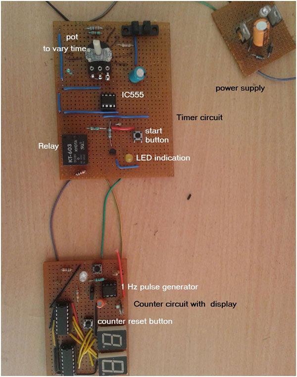
Fig. 1: Digital timer and counter prototypes based on 555 IC
Circuit Description
The circuit is divided into 2 sections
1. Timer Circuit
2. Counter Circuit
Timer Circuit
This is the circuit (see circuit diagram guide) that turns on the relay for a set period of time. It is built using IC555. IC555 is configured in monostable mode. Its time period is determined by the RC components R2 and C3. R2 is a 100K variable resistance, so we can vary the time period. The minimum and maximum time period can be calculated as
T max. = 1.1 × R2 max. × C3
= 1.1 × 101 × 10 3 × 100 × 10 -6
= 11 seconds
ET min = 1.1 × R2 min × C3
= 1.1 × 1000 × 100 × 10 -6
= 0.11 sec.
Observation
For the experiment, the RC values are kept smaller to obtain the time interval in seconds. But by choosing larger values of R and C the time interval can be defined in 10s of a second or also in minutes.
The IC555 output drives three components
· First, it drives LED2 through the current limiting resistor. LED2 is used to indicate that the relay is ON
· Secondly, it drives 1 C/O (switching) relay through the NPN transistor. Any load or machine or device is connected to the C (common) and NO (normally open) terminals of the relay
· Third activates the reset pin of another IC555
Another IC555 is connected in astable mode. Its output frequency is determined by the 100 K pot R5 and the 10 uF capacitor C1. Its frequency is adjusted by 1 Hz by varying potentiometer R5. Therefore, LED1 flashes every 1 second. The output of this IC555 is provided as clock pulse to the counter circuit.
Counter circuit and circuit operation
Counter Circuit
The 2-digit counter circuit is built using two-decade display and counter driver CD4026 chips. The 1 Hz pulse output from IC555 is directly supplied as clock pulse input (pin 1) to 1 st CD4026. (Refer to the 2nd circuit diagram tab)
It increments its count by 1 on each pulse input. It also converts the count to equivalent 7-segment (common cathode) display code so that the count can be displayed. It counts from 0 to 9 and resets back to 0. When it goes from 9 to 0, it generates an output (run) pulse that can be given to the next decade's counter chip. Then, as shown in the figure, the performance (pin 5) of 1 st the decade counter is provided as clock input (pin 1) to 2 and decade counter chip. The outputs of both decade counter chips (CD4026) are a, b, c, d, e, f and g which can be supplied directly to the respective inputs for type 7 common cathode segment displays. The outputs of the CD4026 chip are connected to the abcdefg inputs from both 7-segment monitors as shown. As the count increases, it is displayed on these displays from 00 to 99 and again 00. As they are common cathode type displays, their common terminals are grounded. To reset both chips to 0, you need to pulse the reset pin (#15) high. Therefore, a button is connected to the reset pins of both chips as shown, to reset the counter to 00, normally both reset pins are connected to ground through a 10K resistor.
Circuit Operation
· When power is supplied, the relay and LED1 (yellow) are off. The astable mustivibrator IC is also turned off, so it does not generate 1 Hz pulses. The counter displays 00 in seven segments. Otherwise, pressing the counter reset button may reset it to 00
· Set the desired time between 0.1 to 11 seconds by setting the potentiometer to the appropriate value
· The trigger is applied to the IC555 timer by pressing the start button
· The output of IC555 becomes high. Then the relay is on, which is indicated by the yellow LED
· At the same time, the reset pin of the second IC555 also goes high
· Then it starts generating 1 Hz pulses which are given to the counter
· Therefore, the counter starts increasing every second like 0, 1, 2, ……
· After the set period of time (say 6 seconds) of IC555 timer, its output goes low
· Then the relay is off, LED1 is also off and resets pin 2 and IC555 goes low
· Then it stops generating pulses that make the counter stop counting
· The last count is displayed in 7 segments
· This way we can see how long the relay was ON
· Again set any different time interval by changing pot value and press start button
· The same process is repeated
Circuit diagrams
| circuit1_0_0 | 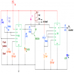 |
| circuit2_4 |  |
Project Components
- The decline in Indian imports