An Mho relay, an admittance or angular admittance relay, is an important protection device in power systems. It is a type of distance relay that works based on measuring the angle of admittance or impedance. The Mho relay provides reliable and selective fault detection and protection by comparing the measured impedance or admittance with a predefined characteristic impedance or admittance limit. The Mho relay determines the distance to the fault location in the power system by analyzing the phase angle and magnitude of the measured values. This relay is widely used in transmission lines and other high voltage applications to ensure the stability and reliability of the power grid. This article explores the principles, operation and applications of the Mho relay and highlights its importance in power system protection.
Construction and operation of Mho relays
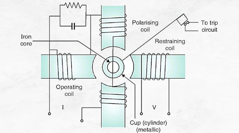
A simple form of Mho relay Admittance or angular admittance relays is shown in the following figure:
It is a kind of cup with electromagnetic induction MHO relay .
The torque equation is T = K 1 VI (Φ – α) – K 2 v 2 –K 3
The upper and lower poles are excited by a voltage V to produce a polarizing flux. The capacitor connected in series provides a storage function. A current excites the left pole as an operating variable. Due to the current I, the left pole interacts with the polarized flux due to V, which is the active torque K 1 VI Cos (Φ – α).
The angle α can be adjusted by adjusting the resistance in Phase shift circuit provided on the left pole. The voltage excites the right pole and its flux interacts with the polarization change to produce the Holding Torque K 2 v 2 .
The Relay mho measures a component of Allow S ∠ θ . But its characteristic, shown in the impedance diagram (i.e. in the RX diagram), is a circle passing through the origin shown in Fig. It is inherently a directional Relay as it only detects the error in the forward direction. The relay is called Mho relay because its characteristic is a straight line when in Intake diagram (GB axes i.e. conductance-susceptance axes) as in the figure.
Read: Directional Overcurrent Relay Read : Solid State Relay or Static Relay
Characteristic expression of the Mho relay
The operating torque for an Mho relay occurs through the VI element and the restraining torque occurs through the voltage element.
Therefore mho relay can be called voltage controlled directional relay .
T = K 1 VI Cos (Φ – α) –K 2 v 2 where the effect of the spring is neglected.
K 2 v 2 < K 1 VI Cos (Φ – α)
K2V 1I cos (Φ – α)
(V/I cos (Φ – α)) 1/K 2 or (V/I) < (K 1 /K 2 ) Cos (Φ – α) or Z < (K 1 /K 2 )Cos (Φ – α)
Under equilibrium conditions, the operating torque is equal to the holding torque.
that is, K 1 VICos (Φ – α) = K 2 v 2
(I/V)Cos (Φ – α) = (K 2 K 1 ) =K
(1/Z) = (K / Cos (Φ – α)) = Y
Y = K / Cos (Φ – α) = admittance in mho.
MHO relay units are used to protect a section of line. Unit I is fast and saves 80 to 90% of line section. Unit II covers the remainder of the line section and its range extends up to 50% of the adjacent line section. Unit III is intended for backup protection of the adjacent line section. Units II and III operate with a preset delay, typically 0.2 to 0.5 seconds and 0.4 to 1 second, respectively. The time interval characteristic is scaled, as shown in the figure.
Impedance Relay and Mho for Power Swing
Comparison of Mho characteristic and impedance characteristic under voltage fluctuations. AB is the line to be protected. The relay with impedance characteristic trips even at fault points behind location A, which is nothing more than a “fault trip”.
Although the relay with Mho characteristic requires a comparatively small circuit area to line AB, it does not detect the errors behind A. Therefore, many points covered by the impedance characteristic are in the negative torque range of the Mho characteristic.
Power swing location and shift mho relay
The location of power fluctuation, which occurs in long transmission lines during false synchronization, etc., and is a transient phenomenon, is a curve that enters the operating range of an impedance relay before that of the Mho relay, a curve in the diagram. This is undesirable because the transmission line will shut down under the protection of the impedance relay before the power fluctuation has a chance to subside. However, if a strong and rapid power fluctuation occurs, the location may enter the operating range of the Mho relay, which intervenes and disconnects the line, which is also undesirable. Therefore, Mho shift relay is used to avoid this situation as shown below.
During power swing, the location of the impedance measured by the relay moves along the curve. When it enters the positive torque range of the Mho offset characteristic (point P), the Mho offset relay is activated and blocks the BC line measuring relay. Therefore, Mho relay does not operate during power swing.
Comparison Table
| S. No |
Relay type |
Actuating Torque Element |
Torque Retaining Element |
Used for protection |
| 1 |
Impedance relay (Z) |
Current (me) |
Voltage (V) |
Phase errors in medium length cables |
| two |
Reactance relay (X) |
Current (I2) |
Voltage – Current SinΦ (V – I sin Φ) |
Earth faults in short cables |
| 3 |
Approval relay (Y) |
VI Cos (Φ – α) |
v |
Phase errors in long cables |