The universal asynchronous receiver/transmitter (UART) is the most common point-to-point (peer) serial communication interface used in microcontrollers. It is a simple two-wire interface that does not require a clock signal or any master device for serial data transmission between two embedded devices. It can transmit data packets of variable length (5 to 9 bits) with the provision of a parity bit for error detection. This is why almost all microcontrollers have built-in USART or at least UART peripherals.
In UART communication, two devices communicate data directly with each other. This data communication can be simplex (where one device is the receiver and another is the transmitter), full duplex (where both devices receive and transmit data to each other simultaneously) or half duplex (both devices transmit and receive data one to each other, but one at a time). A device with a UART peripheral can communicate with another device with a UART peripheral, either directly (if both devices are operating at TTL logic levels) or through a serial driver chip (if one or both devices are operating at other TTL logic levels). signal other than TTL). Serial driver protocols were developed to facilitate long-range data communication. There are three most commonly used UART serial driver protocols –
1) RS-232 – In the RS-232 serial driver protocol, a voltage signal in the range of -25 V to +25 V is used for data communication where the -25 V to -3 V signal is equivalent to the logic HIGH (bit 1 status) and the +3 V to +25 V signal is equivalent to logic LOW (bit 0 status). The RS-232 driver chip (such as MAX232) converts these voltage levels (such as from a PC) to TTL voltage levels (0 to 5V) for data transmission to a TTL device with a UART peripheral (such as a microcontroller). The driver chip (such as MAX-232) similarly receives bits at TTL logic levels from a TTL device with UART peripheral (such as a microcontroller) and converts them to standard RS-232 signal levels for transmission to the device with RS-232 interface (like PC). RS-232 allows point-to-point full-duplex UART communication between two devices. The RS-232 driver chip uses at least three wires (Tx, RX, and Common Ground) to interface with the RS-232 port or interface of a device. In RS-232 protocol, a UART transmitter can communicate data only to a UART receiver.
2) RS-422 – In RS-422 serial driver protocol, voltage signals in the range of -6 V to +6 V are used for data communication, where -6 V to -2 V signal is equivalent to logic HIGH (status of bit 1) and The signal from +2 V to +6 V is equivalent to logic LOW (status of bit 0). The RS-422 driver chip converts these voltage levels into TTL voltage levels (0 to 5V) for transmission to the TTL device with UART peripheral. The driver chip similarly converts bits at TTL logic levels from the TTL device with UART peripheral to standard RS-422 signal levels for transmission to the device with RS-422 interface. RS-422 allows full-duplex and half-duplex UART communication between two devices. The RS-422 protocol uses differential signals (two inverted signals on two lines for transmitting and receiving data at the end device) to provide long-range data with better signal-to-noise characteristics. Therefore, the RS-422 driver chip uses at least 5 wires to connect to the RS-422 port of a device (two Tx, two Rx, and common ground). In RS-422 protocol, a UART transmitter can communicate data to two UART receivers.
3) RS-485 – RS-485 is a half-duplex version of the RS-422 protocol. Generally, RS-422 driver chips can also operate in RS-485 mode. In the RS-485 protocol, a UART transmitter can communicate data to multiple UART receivers.
Devices with a UART peripheral communicate data asynchronously. Instead of using any clock signal, devices with UART peripheral frame data (5 bits to 9 bits long) in a data packet that starts with a start bit and ends with a stop bit. When the UART receiver detects the start bit, it starts searching for data packets at a predetermined frequency called baud rate. The transmission rate is expressed in bauds per second, which means data packets or words communicated per second. Ideally, two devices communicating data through UART peripherals should have the same baud rate. UART peripherals can manage a maximum of 10% tolerance in transmission rates. An optional parity bit can be sent in the UART data packet to detect errors in data communication. The data packets are framed as shown in the following figure by UART devices –

Figure 1: Data packet format in serial UART protocol
In this project, a portable device was designed that can read data (up to 500 bytes) from a UART transmitter and allow the user to inspect the transmitted data on a character LCD. The user can set the baud rate, a number of data bits, parity and stop bit on the device to match the UART transmitter. The user can adjust these parameters on the device until the correct data packets are observed on the screen. In this way, a user can identify the baud rate, number of data bits, parity, and stop bit of the UART transmitter and set the same parameters on an unconfigured UART receiver.
Typically, to check the USART transmission of a microcontroller-based embedded device, the Rx and Tx pins of the controller are connected to the COM PORT of a PC through a serial driver chip (such as MAX232 for RS-232 protocol). Then programs like HyperTerminal are used to verify data transmission. In this method, it is still difficult to check/identify the non-printable characters on the computer screen. The device developed in this project displays data packets read on LCD characters in text, hexadecimal, decimal and octal formats for easy identification of non-printable characters. This device is also capable of communicating a fixed stream of data packets (a test sequence containing characters A to Z and digits 0 to 9) to a UART receiver to determine whether the receiving device is working properly or not.
This device is designed using AVR ATMega8 microcontroller. ATMega8 has programmable Serial USART so it can easily communicate with UART or USART peripheral of any other microcontroller. ATMega8 has internal 512 byte EEPROM which is used to fetch up to 500 bytes of serial data from a UART transmitter for inspection. A 20X4 character LCD was connected to the ATMega8 to display and inspect the fetched UART data packets.
This device was designed to be used in an industrial environment, so the ATMega8 was connected to the MAX485 serial driver chip. MAX485 is a UART serial driver chip that can be used for UART communication with devices with RS-422 or RS-485 interface. The device can also communicate directly with the USART/UART interface of a TTL device (such as other microcontrollers). To read data from devices with an RS-232 interface, the MAX-232 must have an external interface with this device.
Required components –
| Component name | Amount |
| ATMega8 or ATMega8A microcontroller IC | 1 |
| IC MAX485 | 1 |
| 20 x 4 character LCD | 1 |
| 11.0592 MHz Crystal | 1 |
| trimpot 5K | 1 |
| 3mm LEDs | 3 |
| Button switches | 6 |
| 22pF Disc Capacitors | two |
| 0.1uF disk capacitor | 1 |
| 10K ohm 0.25W resistors | 7 |
| 4.7K ohm 0.25W resistor | 1 |
| 3.3K ohm 0.25W resistor | 1 |
| 2.2K ohm 0.25W resistors | two |
| 470 ohm resistor 0.25 W | 1 |
| 100 ohm 0.5 W resistor | 1 |
| 28-pin IC base | 1 |
| 8-pin IC base | 1 |
| 6-pin connector | 1 |
| Berg Belt – Men | 1 |
| Berg Belt – Women | 1 |
| Suitable PCB | 1 |
| AVR Programmer | 1 |
Circuit Diagram –

Fig. 2: Circuit diagram of universal UART data receiver based on ATmega8 AVR and UART tester
Circuit Connections –
This device is based on the AVR ATMega8. ATMega8 is an 8-bit microcontroller that can operate up to 16 MIPS of transfer rate clocked at 16 MHz. ATMega8 is interfaced with a 20X4 character LCD and a MAX485 serial driver chip to make the device. There is a Trimpot (shown as VR1 in the circuit diagram) which is used to adjust the contrast of the LCD. There is a yellow LED interfaced parallel to the entire circuit that is used to indicate that the device is working. There is a red LED connected to bit 2 of Port D of the Atmega8 which is used to indicate that the device is sending test data to a UART receiver. There is a white LED connected to bit 7 of Port D of the ATMega8 which indicates that the microcontroller is active and waiting for a flashing menu button to be pressed.
There are 6 button switches interlocked on port B of the ATMega8 for user input. The device can operate in two modes – 1) Menu Mode which displays baud rate, data bits, parity and stop bit and 2) Preview Mode which displays the data packets fetched from its buffer of a UART transmitter. Button switches are used to change the mode and operate the device in both modes. The buttons are connected to the microcontroller pins through six pull-up resistors.
Serial data settings and control can be operated using these six buttons (shown as SW1 to SW6 in the circuit diagram). The button interfaced to bit 5 of port B (shown as SW6 in the circuit diagram) is a toggle switch used to switch between View mode and Menu mode. The SW2, SW3, SW4 and SW5 buttons have different functions in both modes. The SW1 works in VIEW MODE only to send test data to a UART receiver.
The Rx and Tx pins of the ATmega8 can be used to receive USART/UART data transmission data packets from any microcontroller. The Rx and Tx pin of the ATmega8 also interfaces with the MAX485 serial driver IC. MAX485 can receive UART data from any device with RS-485 or RS422 interface. RS-485 and RS-422 are most commonly used serial communication protocols in industries. To receive UART data from RS-232 interface, this device needs to have external interface with IC MAX232.
The entire circuit operates on 5V DC which can be obtained from a 5V power bank or 9V battery with 5V regulated power supply using 7805 IC. A frequency crystal of 11.0592 MHz is used with ATmega8 to obtain an accurate transmission rate during testing.
How the circuit works –
After assembling the circuit, the ISP port of the ATmega8 must be connected to any AVR programmer and the SerialDataTester.HEX file must be updated on the microcontroller. Then disconnect the AVR programmer circuit. Now the device is ready for operation.
When the device is turned on, the Blinker LED and RX-MODE LEDs light up for a while and the LCD starts displaying the project title and current USART settings. After a few seconds, the LCD displays the message NO DATA or BUFFER EMPTY if there is no data received from a UART transmitter.
The device can now be used to test serial data from a UART transmitter or to test a UART receiver by sending sample data packets. Buttons SW1 to SW6 can be used to navigate through View mode and Menu mode. View mode displays serial data received from a UART transmitter, while Menu mode allows you to adjust UART settings.
1) Menu mode – To test serial data from a UART transmitter, the user first needs to make UART settings on the device. The baud rate, number of data bits, parity and stop bit settings of the device must be the same as that of the UART transmitter to receive data packets correctly. The expected baud rate, number of data bits, parity and stop bit must be set by navigating to menu mode. User can enter menu mode by pressing SW6 button. When pressing the key, the LCD displays the USART menu containing parameters (Baud Rate, Data bits, Parity and Stop Bits) with current values. To select a parameter, the SW4 button must be pressed. The selected parameter is indicated by the blinking cursor. To change the parameter value, the SW5 button must be pressed against the selected parameter. Parameters can be set to the required values using the SW4 and SW5 buttons. Once the parameters have been configured, their values can be saved by pressing the SW3 button. These values are permanently saved in the microcontroller's internal EEPROM. To change the values, if necessary, the user needs to navigate back to menu mode by pressing the SW6 button. The default parameter settings for baud rate, data bits, parity, and stop bit are 9600, 8, 0, and 1, respectively. User can reset USART default settings (9600, 8, 0, 1) by pressing SW2 button.
2) View mode – This is the default mode for viewing received serial data. To switch from Menu mode to View mode, the user needs to press the SW6 button once again or wait 10 seconds without operating any buttons. In Preview mode, four received data packets are shown on four character LCD lines. Each line consists of position, character, hexadecimal code, decimal code and octal code of the serial data packet received in the buffer. If the received data packet is not a printable character, a dot will be displayed in place of the character. The maximum buffer size is set to 500 bytes as the ATmega8 has 512 bytes of built-in EEPROM. The total number of bytes received (in the buffer) is displayed in the lower left corner of the LCD.
In Preview mode, received data packets can be scrolled up and down by pressing the SW5 and SW4 buttons. When pressing the SW3 button, the display shows the data of the first data packet received in the buffer. If the SW2 button is pressed, the received buffer will be cleared and the LCD will display the message “NO DATA or BUFFER EMPTY”.
3) Testing a UART receiver – To test a UART receiver, the user needs to press the SW1 button. When you press this button, a test string containing the characters A to Z and 0 to 9 is transmitted through the Tx pin as well as the A and B pins of the MAX485. When pressing this key, the received buffer is also cleared for receiving new data. The red LED glows for a short period, which is an indication that data is being transmitted from the microcontroller to the UART receiver.
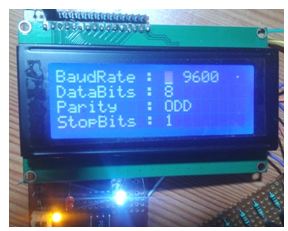
Fig. 3: Image showing menu mode of ATmega8 based UART serial data tester
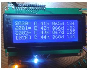
Fig. 4: Image showing the visualization mode of the ATmega8-based UART serial data tester
Programming Guide-
This device is based on AVR ATmega8 and is programmed with embedded C using AVR Studio 4. Other programming tools like Atmel Studio or Notepad++ can also be used to write and compile the code. The ATmega8 is programmed to receive UART settings from the user via buttons and receive serial data from a UART transmitter accordingly. The received data buffer is displayed on a 20X4 character LCD, where received data packets can be scrolled up and down. The ATmega8 is also programmed to test any UART receiver by sending a test string to it.
Constants used in the code-
#define F_CPU 11059200L: – Constant used to define the MCU clock frequency
#define F_CPU_BY_100 F_CPU/100 :- Frequency divided by 100 to calculate the transmission rate.
#define UMS 500: – USART message size initialization for array
#define LCD_P PORTC: – Port C for interfacing with LCD
#define LCD_EN 0b00010000 :- En pin of the LCD connected to the 4th pin of port C
#define LCD_RS 0b00100000 :- LCD Rs pin connected to the 5th pin of Port C
#define BTN_SW6 0b00100000 :- Switch 6 connected to the 5th pin of Port B
#define BTN_SW1 0b00000001: – Switch 1 connected to pin 0 of Port B
#define BTN_SWS 0b00011110 :- Switch for 4 pins 2,3,4,5
#define BTN_SW5 0b00010000 :- Switch 5 connected to the 4th pin of Port B
#define BTN_SW4 0b00001000 :- Switch 4 connected to the 3rd pin of Port B
#define BTN_SW3 0b00000100 :- Switch 3 connected to the 2nd pin of Port B
#define BTN_SW2 0b00000010 :- Switch 2 connected to the 1st pin of Port B
#define TX_L 0b00000100 :- Tx LED connected to the 2nd pin of Port D
#define TX_C 0b00001000: – RX or TX mode enabled on MAX485
#define BLK 0b10000000 :- Flashing LED connected to the 7th pin of Port D which indicates that the MCU is working.
Variable used in code-
unsigned character URD(UMS+1); : – This array is used to read data from USART
char USD = “ABCDEFGHIJKLMNOPQRSTUVWXYZ0123456789”; :-This array is used to send data in USART
char HEX (16) = {'0′,'1′,'2′,'3′,'4′,'5′,'6′,'7′,'8′,'9', 'A' ,'B','C','D','E','F'}; : – This array is used to convert received data into hexadecimal
intUBRL(12)={ 3, 6, 12, 24, 48, 96, 144, 192, 288, 384, 576, 768}; //X 100 :- baud rates to be changed
uint8_t U_B=5; : – typedef unsigned char 8 bits for baud rate
uint8_t U_D=8; : – typedef unsigned char 8 bits for data bits
uint8_t U_P=1; : – typedef unsigned char 8 bits for parity
uint8_t U_S=1; : – typedef unsigned char 8bit for Stop bit
unsigned character USART_RXD=0; :- variable purpose of receiving data
int URDP = 0; : – For the purpose of reading pin data
intUSDP = 0; :- For the purpose of sending pin data
uint8_tUSCH = 1; :- to update USART data
uint8_t VCCH = 1; :- to update the view mode
Header file and libraries used in the code –
#include : – Standard AVR header for input/output
#include : – Standard AVR header to provide time delays
#include : – Standard AVR header for interrupts
#include : – Standard AVR header to handle EEPROM data
Function used in code-
getString: – manipulates string for printing on the LCD
rdE: – Read data from EEPROM
wrE: – Writes data from EEPROM
P_init: – initializing ports for use
LCD_E: – enables LCD pin E
LCD_WN: – to activate and deactivate RS mode
LCD_WCM: – To connect commands
LCD_init: – To initialize the LCD
LCD_WC: – Write character
LCD_WS: – Write string
LCD_CS: – To clean the screen
LCD_POS: – Pauses the cursor
USART_init: – initializes USART
USART_SC: – To send characters
USART_SM: -To set Menu mode
ISR: – To receive data
VUSCR: – See screen configuration
USART_UPD: – USART data update
USART_SD: -Sending USART data
USART_MN: – USART menu can be changed by switch
VWL: – controls buffer data by switches
Algorithm:
The code for this portable UART data receiver/tester works as follows –
1) When the serial data tester circuit is turned on, firstly, ports are initialized that define port B as input, port C as output and the 7 pins of port D as output. Also passes bit zero to “TX_C, TX_L, LCD_RS, LCD_EN“ to make them LOW.
 void P_init ( )

 {

 DDRB = 0x00;

 DDRC = 0xFF;

 DDRD = 0xFE;

 PORTD &= (~TX_C);

 PORTD &= (~TX_L);

 LCD_P &= (~LCD_RS);

 LCD_P &= (~LCD_EN );

 }
2) After the Ports are initialized, the TX_L LED and BLK LED light up for 2000 milliseconds and go out, which indicates that the program has started.
 PORTD = BLK;

 PORTD = TX_L;

 _delay_ms ( 2000 );

 PORTD &= ~BLK;

 PORTD &= (~TX_L);
3) The LCD initializes and prints a welcome message that is displayed to verify that the LCD is working properly.
 LCD_init( );

 LCD_CS ( );

 LCD_POS (1,1);

 LCD_WS ( " SERIAL DATA TESTER " );

 LCD_POS (2,1);

 LCD_WS ( "====================");

 LCD_POS (3,1);

 LCD_WS ( "for USART & MAX485 ");

 LCD_POS (4,1);

 LCD_WS ("communications");
4) Now it reads the current values from EEPROM to update the menu mode and then sets the buffer value received in USART.
 _delay_ms ( 3000 );

 rdE ( );

 _delay_ms ( 100 );

 USART_SM ( );

 know ;

 _delay_ms ( 2000 );
5) In a while loop, the flashing LED stays on to indicate that it is ready to work. Here the USART data is updated and the display mode is also updated on the LCD. Now the user can see the buffer data and serial communication data saved in EEPROM.
 if (USCH)

 USART_UPD ( );


 if (VCCH)

 {

 VUSCR ( );

 _delay_ms ( 200 );

 }
6) When key 1 is pressed in preview mode, it sends data to USART. The user can view the data on the LCD as well as on the UART receiver as serial terminal of a connected PC.
 if ( ( PINB & BTN_SW1 ) == 0 )

 USART_SD ( );
7) When switch 6 is pressed, it displays the menu mode so that the user can change the baud rate, data bits, parity and stop bit settings. If switch 6 is pressed again, it switches the device from menu mode to preview mode, where the buffer data is shown.
 if ((PINB & BTN_SW6) == 0)

 isMenuPressed = 1;


 if ( isMenuPressed )

 {

USART_MN ( );

 LCD_WCM ( 0x0C );

 }

 else

 VWL ( );
Check out the full code and quickly start building this exciting project.
Project source code
//Program to /* filename : SerialDataTester.C author: fhn Dtd: 22-mar-2018 MCU : ATmega8 (A) @ 11.0592 MHz display; LCD 4 rows others: menu driven buttons: 6 */ #define F_CPU 11059200L #define F_CPU_BY_100 F_CPU/100 #include#include #include #include #define UMS 500 #define LCD_P PORTC #define LCD_EN 0b00010000 #define LCD_RS 0b00100000 #define BTN_SW6 0b00100000 #define BTN_SW1 0b00000001 #define BTN_SWS 0b00011110 #define BTN_SW5 0b00010000 #define BTN_SW4 0b00001000 #define BTN_SW3 0b00000100 #define BTN_SW2 0b00000010 #define TX_L 0b00000100 #define TX_C 0b00001000 #define BLK 0b10000000 //================================================ ============================= unsigned char URD(UMS+1); char USD = "ABCDEFGHIJKLMNOPQRSTUVWXYZ0123456789"; char HEX(16) = {'0','1','2','3','4','5','6','7','8','9', 'A' ,'B','C','D','E','F'}; int UBRL(12)={ 3, 6, 12, 24, 48, 96, 144, 192, 288, 384, 576, 768}; //X 100 uint8_t U_B=5; uint8_t U_D=8; uint8_t U_P=1; uint8_t U_S=1; unsigned char USART_RXD=0; int URDP = 0; int USDP = 0; uint8_t USCH = 1; uint8_t VCCH = 1; //================================================ ============================= void getString ( long val, char *str, char fc, int width ) { long v=val,i=0; int nst=0, p=0; long hvl=1; for (int w=0; w =1; i=i/10 ) { if( (v/i)>=1 && nst==0 ) nst = 1; if (nst==1) { str(p++) = (v/i) + '0'; } else { str(p++) = fc; } v = v%i; } str(p)=0; if (str(p-1)==' ') { str(p-1)='0'; } } //================================================ ============================= void rdE ( ) { int rval = 0; rval = eeprom_read_byte ( (void *)1); if ( rval<1 rval>2 ) return; U_S = rval; rval = eeprom_read_byte ( (void *)2); if ( rval<0 rval>2 ) return; U_P = rval; rval = eeprom_read_byte ( (void *)3); if ( rval<5 rval>8 ) return; U_D = rval; rval = eeprom_read_byte ( (void *)4); if ( rval<0 rval>13 ) return; U_B = rval; } //================================================ ============================= void wrE ( ) { eeprom_write_byte ( (void *)1, U_S); _delay_ms(10); eeprom_write_byte ( (void *)2, U_P ); _delay_ms(10); eeprom_write_byte ( (void *)3, U_D); _delay_ms(10); eeprom_write_byte ( (void *)4, U_B);; _delay_ms(10); } //================================================ ============================= void P_init ( ) { DDRB = 0x00; DDRC = 0xFF; DDRD = 0xFE; PORTD &= (~TX_C); PORTD &= (~TX_L); LCD_P &= (~LCD_RS); LCD_P &= (~LCD_EN ); } //================================================ ============================= void LCD_E ( ) { LCD_P = LCD_EN; _delay_us(10); LCD_P &= (~LCD_EN ); _delay_us(15); } //================================================ ============================= void LCD_WN ( unsigned char nibl , unsigned char RS) { LCD_P &= 0xF0; _delay_us(5); if ( nibl > 0b00001111) LCD_P = ( (nibl>>4) & 0x0F); else LCD_P = (nibl & 0x0F); if (RS) LCD_P = LCD_RS; else LCD_P &= (~LCD_RS); LCD_E ( ); } //================================================ ============================= void LCD_WCM ( unsigned char cmd ) { LCD_WN ( cmd & 0xF0 , 0); LCD_WN ( cmd & 0x0F , 0); _delay_us(2); } //================================================ ============================= void LCD_init() { unsigned char initval = 0x20; _delay_ms ( 50 ); LCD_WN ( 0x30 , 0); _delay_ms ( 20 ); LCD_WN ( 0x30 , 0); _delay_us ( 200 ); LCD_WN ( 0x30 , 0); _delay_ms ( 100 ); LCD_WN ( 0x20 , 0 ); _delay_ms ( 25 ); initval = 0b00001000; initval = 0b00000100; LCD_WCM ( initval ); _delay_ms ( 25 ); LCD_WCM ( 0x0C ); _delay_ms ( 25 ); LCD_WCM ( 0x06 ); _delay_ms ( 250 ); } //================================================ ============================= void LCD_WC ( unsigned char c ) { LCD_WN ( c & 0xF0 , 1); LCD_WN ( c & 0x0F , 1); _delay_us(1); } //================================================ = void LCD_WS ( char s ) { for (int i=0; s(i)!=0; i++) { LCD_WC ( s(i) ); _delay_us ( 5 ); } } //================================================ ============================= void LCD_CS ( ) { LCD_WCM ( 0x01 ); _delay_ms(3); } //================================================ = void LCD_POS ( unsigned char R, unsigned char C ) { switch (R) { case 3: LCD_WCM ( 0x94 + C-1 ); break; case 4: LCD_WCM ( 0xD4 + C-1 ); break; case 2: LCD_WCM ( 0xC0 + C-1 ); break; case 1: default: LCD_WCM ( 0x80 + C-1 ); break; } _delay_ms ( 3 ); } //================================================ ============================= int USART_init (int bd, int db, int prt, int stb) { int ubrr = 0; int bd_rate=bd; unsigned int ucsrc = (1< =0) { UBRRL = ubrr; UBRRH = (ubrr>>8); } else return (-1); UCSRB = (1< break; case 6: ucsrc = (1< break; case 7: ucsrc = (2< break; case 8: ucsrc = (3< break; default: return (-1); } if (stb==2) ucsrc = (1< getString(UBRL(U_B), str,' ', 3); LCD_WS (str); LCD_WS ( "00" ); LCD_POS ( 2,1 ); LCD_WS("DataBits:"); LCD_POS ( 2.12 ); LCD_WC ( U_D+'0'); LCD_POS ( 3,1 ); LCD_WS ( " Parity : " ); LCD_POS ( 3.12 ); switch(U_P) { case 1: LCD_WS ( "ODD " ); break; case 2: LCD_WS ( "EVEN" ); break; default:LCD_WS ( "NONE" ); break; } LCD_POS ( 4,1 ); LCD_WS ( "StopBits : " ); LCD_POS ( 4.12 ); LCD_WC ( U_S+'0'); LCD_POS ( 1.12 ); } //================================================ ============================= ISR (USART_RXC_vect) { USART_RXD = UDR; if (URDP < UMS) { URD(URDP++) = USART_RXD; } } //================================================ ============================= void VUSCR ( ) { char str(10); LCD_CS ( ); if (URDP<=0) { LCD_POS (2,1); LCD_WS ( "NO DATA or" ); LCD_POS (3,1); LCD_WS ( "BUFFER EMPTY" ); return; } for ( int i=0; i<4 && URDP>(USDP+i); i++ ) { LCD_POS ( i+1 , 1 ); LCD_WC ( '@' ); getString(USDP+i, str,'0',3); LCD_WS (str); LCD_WS ( " = " ); if (URD(USDP+i)<32 URD(USDP+i)>126 ) LCD_WC ( '.' ); else LCD_WC ( URD(USDP+i) ); LCD_WC ( ' ' ); LCD_WC ( HEX(URD(USDP+i)/16) ); LCD_WC ( HEX(URD(USDP+i)%16) ); LCD_WS ( "h " ); getString(URD(USDP+i), str,'0',3); LCD_WS (str); LCD_WS ( "d " ); int n = URD(USDP+i); LCD_WC ( n/64 + '0' ); n = n%64; LCD_WC ( n/8 + '0' ); LCD_WC ( n%8 + '0' ); } LCD_POS(4,1); LCD_WC ( '(' ); getString(URDP, str,'0', 3); LCD_WS (str); LCD_WC ( ')' ); } //================================================ ============================= void USART_UPD ( ) { USART_init (UBRL(U_B), U_D, U_P, U_S ); URDP=0; USDP = 0; VCCH = 1; wrE ( ); rdE ( ); } //================================================ ============================= void USART_SD ( ) { LCD_CS ( ); PORTD = BLK; LCD_POS (1,1); LCD_WS ( "SENDING.... " ); PORTD = TX_C; PORTD = TX_L; _delay_ms(10); LCD_POS ( 2,1 ); for (int i=0; USD(i)!=0 ;i++) { if (i==18) LCD_POS ( 3,1 ); LCD_WC ( USD(i) ); USART_SC ( USD(i) ); _delay_ms(1); } _delay_ms(50); PORTD &= (~TX_C); LCD_POS (4,1); LCD_WS ( "SENT (Check LSB)" ); _delay_ms(50); PORTD &= (~TX_L); _delay_ms(1500); VCCH = 1; } //================================================ ============================= void USART_MN ( ) { uint8_t wtl = 100; uint8_t btn_sws = 0; uint8_t editpos = 0; char str(10); uint8_t sU_B = U_B; uint8_t sU_D = U_D; uint8_t sU_P = U_P; uint8_t sU_S = U_S; USART_SM ( ); _delay_ms ( 300 ); LCD_WCM ( 0x0F ); while ( wtl > 0) { PORTD ^= BLK; LCD_POS (editpos+1,12); btn_sws = PINB & BTN_SWS; if ( btn_sws != BTN_SWS) { wtl = 100; _delay_ms ( 300 ); if ( ( btn_sws & BTN_SW4 ) ==0 ) { editpos++; if (editpos>3) editpos = 0; _delay_ms ( 300 ); } else if ( ( btn_sws & BTN_SW5 ) ==0 ) { switch (edits) { case 0: sU_B++; if (sU_B>11) sU_B=0; LCD_POS ( 1.12 ); getString(UBRL(sU_B), str, ' ', 3); LCD_WS (str); LCD_WS ( "00" ); break; case 1: sU_D ++; if (sU_D>8) sU_D=5; LCD_POS ( 2.12 ); LCD_WC ( sU_D +'0' ); break; case 2: sU_P++; if (sU_P>2) sU_P=0; LCD_POS ( 3.12 ); switch(sU_P) { case 1: LCD_WS ( "ODD " ); break; case 2: LCD_WS ( "EVEN" ); break; default:LCD_WS ( "NONE" ); break; } break; case 3: sU_S ++; if (sU_S>2) sU_S=1; LCD_POS ( 4.12 ); LCD_WC ( sU_S +'0' ); break; default: break; } } else if ( ( btn_sws & BTN_SW3 ) ==0 ) { U_B = sU_B; U_D = sU_D; U_P = sU_P; U_S = sU_S; USCH = 1; USART_SM ( ); LCD_POS ( 4.15 ); LCD_WS ( "SAVED" ); _delay_ms ( 2000 ); return; } else if ( ( btn_sws & BTN_SW2 ) ==0 ) { U_B = 5; U_D = 8; U_P = 1; U_S = 1; USCH = 1; USART_SM ( ); LCD_POS ( 4.15 ); LCD_WS ( "RESET" ); _delay_ms ( 2000 ); return; } } else { wtl--; } if ((PINB & BTN_SW6) == 0) { wtl = 0; _delay_ms ( 300 ); } _delay_ms ( 100 ); } VCCH = 1; } //================================================ ============================= void VWL ( ) { int btn_sws = 0; PORTD ^= BLK; btn_sws = PINB & BTN_SWS; if (( btn_sws & BTN_SW2 ) == 0 ) { URDP=0; USDP = 0; VCCH = 1; _delay_ms ( 100 ); } else if ( ( btn_sws & BTN_SW4 ) == 0 ) { USDP += 3; if (USDP>=URDP) USDP = URDP-1; VCCH = 1; _delay_ms ( 100 ); } else if (( btn_sws & BTN_SW5 ) == 0 ) { USDP -= 3; if (USDP<0) USDP = 0; VCCH = 1; _delay_ms ( 100 ); } else if ( ( btn_sws & BTN_SW3 ) == 0 ) { USDP = 0; VCCH = 1; _delay_ms ( 100 ); } } //================================================ ============================= int main() { int isMenuPressed = 0; int user_recd_data_pos = -1; P_init ( ); PORTD = BLK; PORTD = TX_L; _delay_ms ( 2000 ); PORTD &= ~BLK; PORTD &= (~TX_L); LCD_init( ); LCD_CS ( ); LCD_POS (1,1); LCD_WS ( " SERIAL DATA TESTER " ); LCD_POS (2,1); LCD_WS ( "===================="); LCD_POS (3,1); LCD_WS ( "for USART & MAX485 "); LCD_POS (4,1); LCD_WS ("communications"); _delay_ms ( 3000 ); rdE ( ); _delay_ms ( 100 ); USART_SM ( ); USCH = 1; VCCH = 1; know ; _delay_ms ( 2000 ); while(1) { PORTD ^= BLK; if (usart_recd_data_pos != URDP) VCCH = 1; usert_recd_data_pos = URDP; if (USCH) USART_UPD ( ); if (VCCH) { VUSCR ( ); _delay_ms ( 200 ); } isMenuPressed = 0; USCH = 0; VCCH = 0; _delay_ms ( 50 ); if ( ( PINB & BTN_SW1 ) == 0 ) USART_SD ( ); if ((PINB & BTN_SW6) == 0) isMenuPressed = 1; if ( isMenuPressed ) { USART_MN ( ); LCD_WCM ( 0x0C ); } else VWL ( ); } return 0; } //================================================ ============================= ###
Circuit diagrams
| AVR-ATmega8-Universal-UART-Data-Tester-1 | 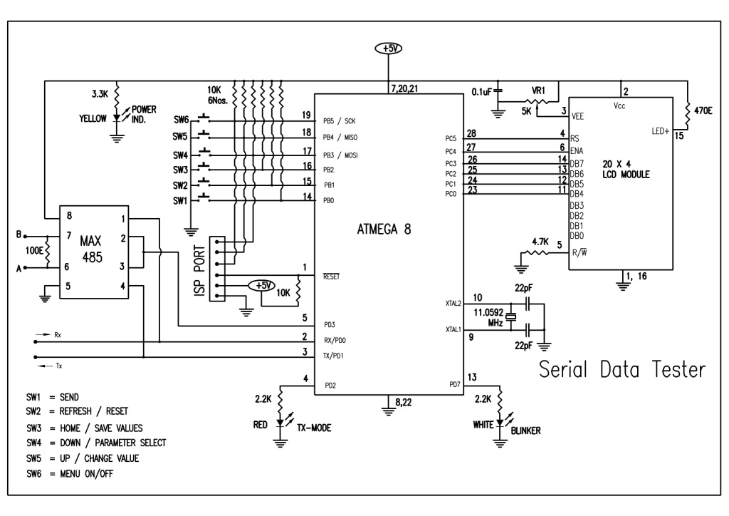 |