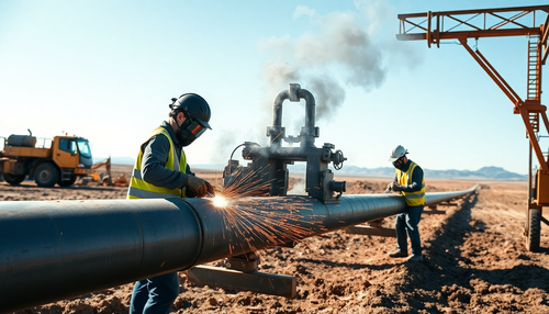
Types of faults that must be protected in engines
-
Stator error
-
Rotor error
-
Overloaded
-
Unbalanced supply voltages, including single-phase
-
under tension
-
Reverse or idle start
-
Loss of synchronism (only for synchronous motors)
Engine stator protection

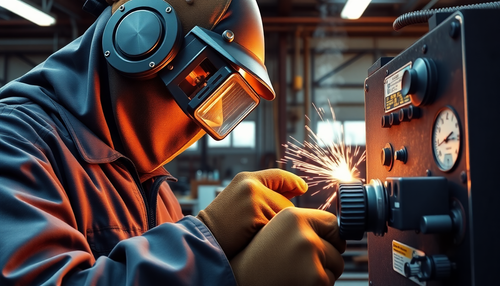
Engine rotor protection
Motor overload protection
The wide variety of engine applications and designs makes it very difficult to cover all engine types and performances with a specific characteristic curve. Overload protection is designed to be as close to the heating curve of most motors as possible. The protection characteristic curve must be just below the heating curve of the protected motor. The protection should preferably have adjustable characteristics so that it can be adapted to different engine designs and other applications. The protection must not allow the motor to start after tripping while the winding temperature is still high, as this could have dangerous consequences. To be effective protection, ideal protection must not allow the motor to restart after a trip.
At the same time, the winding temperature is still high, as this can have dangerous consequences. To provide effective protection, the ideal protection must match the rotor's heating characteristics and its cooling function. It is also necessary to ensure that the relay is not operated with high starting currents, up to six times the full load current, which may take a few seconds, half a minute or even longer in exceptional cases. The thermal time constant of most engine types is 15 to 20 minutes; therefore, the relay must have these for overload protection.

Unbalanced delivery voltages, including single-phase voltage
Unbalanced supply voltages, including single-phase, pose significant challenges in electrical systems and can lead to various problems. When the supply voltages supplied to an electrical system are not evenly balanced, the voltages between the different phases will be unequal. This situation can occur due to several factors such as: B. faulty connections, downed power lines or problems with the distribution transformer.
A common problem associated with unbalanced supply voltages is single-phase. Single-phase refers to the condition in which one of the phases of a three-phase system is lost or separated. This leads to an imbalance in the electrical charge on the remaining two phases, which can have serious consequences.
In electric motors, for example, unbalanced supply voltages can lead to an increase in the current flowing through the motor windings. Unstable power distribution can cause overheating and, as a result, engine damage.
Unbalanced supply voltages can also affect other electrical devices such as transformers, generators and electronic devices. Uneven voltages can lead to increased stress on components, leading to premature aging, increased losses and reduced service life.
Below volume Old T
Undervoltage refers to a situation where the voltage supplied to an electrical system or device drops below expected levels. The reason for this can be several factors, such as: B. fluctuations in the power grid, equipment malfunction or high power demand that exceeds the capacity of the power source. Undervoltage can have significant effects on the operation of electrical devices and systems.
Undervoltage can cause reduced performance and reduced performance of electrical devices. Many electrical devices and machines require a certain voltage range to function optimally. If the voltage drops below this range, devices may not function as expected. For example, motors may experience a drop in torque and speed, resulting in reduced performance and potentially affecting industrial processes or equipment functionality.

Undervoltage can also cause overheating in electrical devices. Devices may draw higher currents at lower voltage than normal to compensate for reduced power. Increased current flow can lead to increased temperature within the device, resulting in overheating and possible damage. Over time, repeated exposure to stress can lead to accelerated wear, reduced service life, and increased maintenance and replacement costs.
Vice versa or Open phase starting.
Reverse or open phase starting refers to the situation in which a three-phase motor is started with one or more phases in reverse order or completely separated, resulting in incorrect motor operation. This condition may occur due to wiring errors, faulty connections, or damaged components. Reverse or open phase starting can damage the motor and connected devices.
When a motor is started with reversed or open phases, the normal direction of rotation of the motor may be reversed. This can cause mechanical stress on the engine and driven equipment and potentially cause damage to gears, belts or other transmission components. Furthermore, the reverse direction of rotation can lead to loss of efficiency and reduced engine performance, which in turn leads to increased energy consumption and reduced productivity.
Loss of syn C chronology
Loss of synchronization refers to a condition that occurs specifically in synchronous motors when the rotor speed is no longer synchronous or can no longer be kept synchronous with the rotating magnetic field generated by the stator. Synchronous motors are designed to operate at a specific synchronous speed, which is determined by the frequency of the power supply and the number of poles in the motor.
Loss of synchronization causes the rotor to become out of sync with the rotating magnetic field, resulting in erratic operation and reduced engine performance. A common cause of loss of synchronization is a sudden change in load. If the engine experiences a sudden increase in load or an abrupt reduction in torque demand, it may not be able to maintain the required speed and may become out of sync. This can result in mechanical stress, increased vibration and possible damage to the motor or driven equipment.