Stators play a crucial role in the operation of electrical machines such as generators and motors by creating a stationary magnetic field that interacts with the rotating magnetic field of the rotor. However, stators are susceptible to failures that can affect their performance and lead to costly downtime. A significant fault that compromises stator integrity is turn-to-turn short circuits, which occur when the insulation between each turn of the stator windings is damaged or fails. Turn-to-turn faults can result in short circuits, unbalanced currents and excessive heating, compromising the reliability and overall efficiency of the machine. Therefore, protecting stators from short circuits has become a critical concern in the industry.
Stator winding short circuit protection
The percentage differential protection relay can never detect inter-turn faults or inter-turn faults in the same stator phase winding (also called modified Merz-Price differential relay). This occurs because the current that these defects produce flows in a local circuit between the affected windings and does not produce a difference between the currents entering and leaving the winding at the two ends where the current transformers are placed.
If this stator only has one coil per slot, short winding cannot occur. With multiple coils per slot Turn-to-turn failure is likely to occur.
Therefore, instead of a series differential relay, this Cross Differential Relay is used to detect shorted stator winding .
In multi-winding stators, such as those used in hydroelectric generators, each phase winding is split in half due to the high currents they must carry.

Parallel Wound Generator
The schematic diagram of a pre-charged transverse differential protection for shorted stator winding is shown in the figure above.
Generator with a single winding per phase vector and an inaccessible parallel winding

Limited protection against earth faults through differential system
If the neutral wire of the generator is firmly grounded, it can protect complete windings from phase-to-ground error .
As the neutral is grounded through a resistor to limit the ground fault current, with this type of grounding it is impossible to protect the entire winding from the ground fault and the percentage of the winding covered depends on the value of the grounding resistance of the neutral and the context relay. The configuration must be such that protection does not work for Earth Faults on the EHV page. Ground faults are unlikely to occur near the neutral where the relative voltage to ground is lowest. Typically, about 80 to 85% of the generator winding is protected against ground faults. The differential relay leaves the remaining 20 to 15% of the neutral side winding unprotected. Therefore, a separate Earth Fault Protection is intended to protect the entire winding against earth faults.

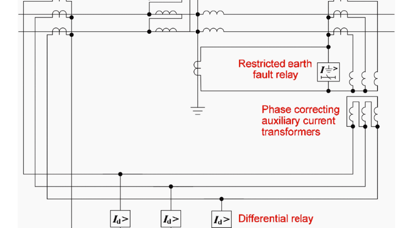
If there is a ground fault in the generator winding (GW), the ground fault current I F flows through part of the winding and is neutral with respect to the ground circuit. The corresponding IS secondary current flows through the operating coil (OC) and the Limited Earth Fault (REF) Differential Protection Relay coil as shown in the figure above.

If the earth fault I F occurs at point F of the generator winding, V af can generate earth fault current I F through the neutral connection to earth. If point 'F' is closer to 'a', i.e. closer to neutral, the excitation voltage is V af is relatively low. Therefore, the earth fault current is I F will be small. It is impossible to keep the relay setting too sensitive to detect small magnitude earth fault currents. Therefore, in practice, around 85% of the generator winding is protected against phase-to-ground faults and the 15% is unprotected by differential protection against earth faults.
Conclusion
In summary, the implementation of protection systems against rotational faults and earth faults is essential to maintain the integrity and longevity of the stators. Through careful monitoring and timely intervention, these advanced defense mechanisms protect the heart of electrical systems, preventing potential failures and catastrophic failures. By protecting stators against insider threats, we ensure uninterrupted power supply and improve the overall reliability of electrical infrastructure. As technology advances, it is critical to continue exploring new ways to protect stators, introduce innovative solutions and promote the resilience of these important components. With the combined efforts of engineers, researchers and industry experts, we can shape a future where stators withstand harsh conditions, deliver consistent performance and power our world with unwavering reliability.

