Why a PCB?
This tutorial will help you understand the need for PCB. Here, I have described the evolution of PCB in different stages. Connecting a circuit without any soldering gun or breadboard is a complex process. I tried to connect an amplifier circuit with a transistor, four resistors and three capacitors, which you can see in the video. Connecting electronic components directly using wire is known as a “discrete circuit”.

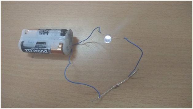
Fig. 1: Image of a simple LED circuit
In the image above, it can be seen that a single 5mm lead wire LED and a 1K resistor are connected to two 1.5V Duracell batteries. This is a small and simple example of a discrete circuit. To explain the concept in detail, I am choosing another simple circuit, an RC amplifier circuit.
In the image below, we can see the RC amplifier circuit with one transistor, four resistors and three capacitors.

Fig. 2: Image of a circuit diagram drawn on paper
I am selecting components such as a BC558 transistor, two 1k resistors, a 10K resistor, a 330ohm resistor, two 0.1uF capacitors and a 10uF electrolytic capacitor. Here I tried to connect these components directly with their conductors and wires. After finishing the circuit it looks similar to the image below.

Fig. 3: Image of components placed in the circuit diagram
We can also connect the circuit with wires to make it less clumsy. Additionally, the following deficiencies may be observed in the circuit:
1. Although the circuit works, it looks clumsy.
2. It has many loose connections, so the output may fluctuate.
3. Sufficient short circuit possibilities. Therefore, it is not safe and therefore precautions are necessary.
4. Reliability is very low.
5. The physical resistance of the circuit is very low.
To avoid complications in circuit connections, we need to fix the components on a plane or any surface. After that we can connect the circuit using wires.
Here I tried to fix these components on thin paper. To avoid complications in the circuit, I drew the component positions correctly. Take a look at the figure below.

Fig. 4: Image of component icons drawn on paper
After attaching the components to the paper and finishing the circuit, I discovered that it looks good, but only on top. If we turn the paper over, the components on the bottom side will again become very messy. But that doesn't matter, as everything will become clear after connecting the circuit. However, it is still incomplete because using this method I only solved the clumsiness of the circuit. But the remaining problems still exist.
Now let's move forward and fix the remaining issues as well. To begin with, I connected the circuit to a thick cardboard board to give the circuit some physical resistance. To do this, I drew the positions of the components on the board and drilled holes to place them. After fixing these components, I connected the cables to the bottom of the board. At this stage, the board looks like the figure below:

Fig. 5: Image of a PCB with soldered components

Fig. 6: Image showing soldering of components on a PCB
After finishing the circuit on the cardboard, we can see that the loose connections have been corrected. However, there is still the problem of short circuit that needs to be resolved.
So, to completely avoid loose connections and possibilities of short circuits, I started connecting and soldering these points using wires. Please see the figure below.

Fig. 7: Image showing the soldering of components on a printed circuit board with wires
Although it looks better than the previous one, it is just a wired board and not a printed circuit board. So to solve the problem we can print all these wire connections on this board. Just look at the figure below of a printed circuit board with all the components and connections.

Figure 8: Image of a commercial PCB
This is what it looks like! Therefore, we use PCB i.e. printed circuit board to keep the circuit simple and reliable.
Here is the video

