Monitoring weather conditions is an important task in many human activities. There are several fields like agriculture, tourism, transportation, etc., which are affected by climate change. Considering the importance of weather monitoring, there are global platforms that monitor weather conditions around the world. These platforms are IoT ecosystems that can be accessed online. It is possible to design custom electronic devices that can connect to such platforms and fetch weather-related data from the cloud platform.
One such global platform is Open Weather Map. Open Weather Map is an online service that provides weather data to web services and mobile applications. It provides over 1 billion predictions every day across the world. There are more than a million users of this platform and thousands of new subscribers are added every day. The platform provides more than 20 APIs for rendering weather-related data. In this project, a device based on ESP8266 will be designed that can connect to one of the APIs provided by Open Weather Map and thus display meteorological data on an LCD display.
The IoT device designed here is a weather station built by interfacing a character LCD with the ESP8266 board. The device searches for meteorological data from the location where it is installed and displays it on the LCD screen. It should be noted that there are no sensors used in this device and the device gets the weather data from an IoT platform i.e. Open Weather Map. The device fetches temperature and precipitation information using API keys and show on the LCD. The ESP8266 is a Wi-Fi modem and can connect to a Wi-Fi hotspot or router by knowing the SSID and password. Using the API key, the ESP module can access data from the IoT service. The ESP8266 is an Arduino compatible module. It needs to be loaded with firmware that can fetch data received over the Internet and display it on the LCD screen. Arduino UNO is used to update the firmware code on the ESP8266 module. The ESP module can also be updated with code using an FTDI converter like CP2102. The firmware itself is written in the Arduino IDE.

Figure 1: Weather station prototype based on ESP8266 and OpenWeatherMap
Required components –

Fig. 2: List of components required to make weather stations based on ESP8266 and OpenWeatherMap
Block diagram –

Fig. 3: Block diagram of weather station based on ESP8266 and OpenWeatherMap
Circuit Connections –
The weather monitoring IoT device designed in this project is built by connecting a character LCD to the ESP8266 module. The ESP-01 model is used in this project which has only two GPIO pins. It is not possible to interface a character LCD with only two GPIO pins. Therefore, an 8-bit I/O expander for I2C bus – PCF8574P is used to interface the LCD with the PES modem. The ESP modem can connect to any Wi-Fi access point by itself. To program the ESP module, it is connected to the PC via FTDI type CP2102 USB converter. After the code is written to the module, it is powered by a voltage regulator circuit.

Fig. 4: Image showing circuit connections of ESP8266 and OpenWeatherMap-based weather station
The device has the following components connected as mentioned –
ESP8266 Wi-Fi Modem – The ESP8266 Wi-Fi modem itself controls the functionality of the device. It must be loaded with program code that can access the API and control the LCD. The firmware code is written using Arduino IDE. It is loaded onto the ESP8266 board using the FTDI USB to serial converter. A generic ESP8266 board is used in this project. This board does not have startup resistors, voltage regulator, reset circuit and USB serial adapter. The ESP8266 module operates with a 3.3 V power supply with a current greater than or equal to 250 mA. Therefore, the CP2102 USB to Serial Adapter is used to supply 3.3V voltage with enough current to run the ESP8266 reliably in all situations.
The ESP8266 Wi-Fi Module is an independent SOC with integrated TCP/IP protocol stack that can access to a Wi-Fi network. The ESP8266 is capable of hosting one application or off-loading all Wi-Fi network functions from another application processor. Each ESP8266 module comes pre-programmed with AT command set firmware. The module is available in two models – ESP-01 and ESP-12. The ESP-12 has 16 pins available for interfacing, while the ESP-01 only has 8 pins available for use. The ESP-12 has the following pin configuration –

Fig. 5: Table listing the pin configuration of the ESP8266 ESP-12 module
The ESP-01 model is used in the project. The ESP-01 model has the following pin configuration –

Fig. 6: Table listing the pin configuration of the ESP8266 ESP-01 Module
The module 's Chip Enable and VCC pins are connected to 3.3 VDC while the ground pin is connected to common ground. The chip enable pin is connected to VCC via a 10K pull up resistor. The RESET pin is connected to ground via a tactile switch where the pin is powered by VCC via a 10K pull up resistor by default. The GPIO-0 pin of the module is connected to ground via a tactile switch where the pin is supplied to VCC via a 10K pull up resistor by default. These pull-up resistors act as voltage divider circuit that protects the ESP8266 board from high voltage.
The CP2102, which is a single chip USB to UART bridge, is used to load firmware into the PES modem. It also provides power supply to the ESP module while boot charging . A CP2102 IC has the following pin configuration –

Fig. 7: Table listing the pin configuration of the CP2101 USB to UART chip

Fig. 8: Table listing the pin configuration of the CP2101 USB to UART chip

Fig. 9: Table listing the pin configuration of the CP2101 USB to UART chip
The ESP board is connected to CP2102 for boot charging mode and usage purpose. For bootloading , the TX pin of the ESP-01 is connected to the RX pin of the CP2102 and the RX pin of the ESP is connected to the TX of the CP2102 so that both can send and receive the data. The ESP8266-01 needs 3.3V power supply, so the VCC of the ESP is connected to the 3V3 of the CP2102 and the GNDs of both need to be connected to each other. The reset pin of ESP8266 along with the 10k pull-up resistor (bootstrap resistor) is connected to the RTS pin of CP2102. GPIO0 is a programming pin used to put the ESP-01 into programming mode. The GPIO0 along with the 10K pull-up resistor is connected to the DTR pin of CP2102. The CHPD pin of the ES-01 is pulled up with a 10 mil resistor. The circuit connections between the ESP module and the CP2102 are summarized in the following table –

Fig. 10: Table listing the circuit connections between the ESP8266 ESP-01 Modem and the CP2101 Module
After connecting the ESP module to the CP2102 adapter, the adapter must be connected to the PC and the ESP module must be loaded with the firmware code.
During code compilation, the GPIO0 and RESET switches must be pressed. To upload the program, the RESET key must be released while the GPIO0 programming key must be left pressed, so that the ESP can enter programming mode. After uploading the code, the programming key must also be released.
So, write the firmware code in Arduino IDE and connect the FTDI converter with PC via USB cable. Open the Arduino IDE and go to Tools->Port and select the Arduino board (Arduino UNO). It might look like /dev/ttyABM0 (Arduino/ Genuine One). Select the correct port name. The port name may be different in different IDE configurations. Then open the serial monitor in the Arduino IDE by navigating to Tools->Serial Monitor and set the baud rate to 115,200 bauds per second. Pass the 'AT' and 'AT+GMR' commands to test the connection between the Arduino and the ESP-01 module. Try different settings for the serial monitor 'End of Line' option, such as NL and CR. Try different combinations until the ESP module starts to interact correctly with the serial monitor.
Download Python, PIP and ESPtool. Erase the preloaded firmware if the ESP module has any. Update the firmware code for the ESP-01 module by writing commands to the serial monitor according to ESPtool instructions. Check out the following link to write the proper command to update the firmware code using ESPtool –
ESPtool commands
To upload the program, the RESET switch must be released while the GPIO0 programming switch must be left pressed. After loading the code, the programming key must also be released. GPIO2 is an alternative TX for bootloader mode.
Remove the connections. Now the ESP module is ready to be installed in the project circuit. After loading the code, the ESP module will automatically access the Wi-Fi point with the SSID provided in the firmware. In the project circuit, the ESP8266 interfaces with the character LCD via the PCF8574P I/O expander.
PCF8574 I/O Expander – The PCF8574 I/O expander is used to interface the LCD with the ESP modem. The PCF8574/74A provides general-purpose remote I/O expansion via the two-wire bidirectional I2C bus (serial clock (SCL), serial data (SDA)). The devices consist of eight quasi-bidirectional ports, 100 kHz I2C bus interface, three hardware address inputs, and interrupt output operating between 2.5 V and 6 V. The quasi-bidirectional port can be independently assigned as an input to monitor the interrupt status or keyboards. , or as an output to activate indicator devices such as LEDs. The system master can read from the input port or write to the output port through a single register. The PCF8574P has the following pin configuration –

Fig. 11: Table listing the PCF8574P pin configuration
The LCD display is connected to the PCF8574P which connects the display to the PES modem. The SDA (Pin 14) and SCL (Pin 15) pins of the IC are connected to the GPIO01 and GPIO2 of the ESP8266 respectively. The LCD module circuit connections with the PCF8574P are summarized in the table below –

Fig. 12: Table listing circuit connections between PCF8574P and LCD Module
Power Source – Once the ESP modem is loaded with the firmware code, it will be connected into the main circuit. In the circuit it is powered by a battery or any other DC power source. The Modem requires 3.3 V DC to operate. Battery power is regulated to 3.3V DC using 1117 IC. The battery supply is connected to the Vin pin of the IC while the regulated voltage is drawn from the Vout pin. The IC tuning pin is grounded. There are two 10 uF capacitors connected to the input and output pins to smooth out any ripples.
How the circuit works –
Once the modem is installed in the device and turned on, it will start searching for the available Wi-Fi hotspot. It connects to a Wi-Fi access point using the SSID and password encoded in the firmware code. The ESP module is now ready to fetch data from the Open Weather Map service. It connects to OpenWeatherMap.org with an open source API. The API provided by Open Weather Map can be used to access a variety of weather-related data for a location. Check out the available data from the Open Weather Map API at the following website link –
OpenWeatherMap API
The ESP modem is programmed to request weather data, i.e. current temperature and humidity of a location from OpenWeatherMap.org. An HTTP request via the POST method is sent to the cloud service, which it responds to by sending back weather data in JSON format. The device must be subscribed to the Open Weather Map website API.

Fig. 13: Screenshot of the OpenWeatherMap API website
When you click on the sign up button, the website navigates to the plans available for the service. The free plan is used here for demonstration purposes.
Then the data retrieved from the website is displayed on the LCD screen. In this plan, weather data updates every 2 hours and 5-day forecast can be accessed.

Figure 14: Screenshot of OpenWeatherMap API plans
When clicking on the get API and start button, the website navigates to a wizard where developer needs to sign up to get the API key.

Fig. 15: Screenshot of the OpenWeatherMap API subscription
Registration can be done with an email ID. After signing up, the developer can use the API key to access the weather data. The API key provided upon successful subscription is used in the firmware to access the weather data.

Fig. 16: Screenshot of the OpenWeatherMap API sign-up page
The weather data obtained from the cloud service is grouped into suitable strings and displayed on the LCD module. The ESP modem sends the data to the LCD module in two-wire protocol which is converted into parallel data using the PCF8574P I/O expander.
Programming guide –
The ESP code starts by importing the necessary libraries. The header files It is are imported. The library is used by the ESP modem to ping the JSON file, while the library allows you to connect and configure a Wi-Fi connection.

Figure 17: Screenshot of C code used for initialization in ESP modem-based IoT weather station
The following settings need to be managed in the firmware code –
a) Initialization of Variables to store the received data.
a) Wi-Fi connection initialization with Wi-Fi Name and Password using SSID and Password variables.
b) Define API key to access meteorological data and configure the language.
These settings are made in the Setup function. A serial connection is started using Serial.begin(115200). The baud rate is set to 115200 for serial communication. The same baud rate must be set in the Serial Monitor of the Arduino IDE to see the response output of the ESP8266. Wi-Fi connection is configure by the following code –
Wifi.begin( SSID password);
While the ESP is still connecting, there is still some delay, so some messages and thresholds are printed on the LCD while the modem connects to an access point or router. These points can be viewed after logging into the serial terminal. It's just a way to see that the little ESP is trying to connect. Then the LCD initializes to display weather data.

Figure 18: Screenshot of the C code used in the ESP modem-based IoT weather station configuration function
The loop function runs after the setup function and iterates infinitely. In the loop function, the getWeatherData function is called where it connects to api.openweathermap.org to fetch the weather data which is in JSON format with respect to the specific city. Then the collected data is stored in the previously declared global variables. The collected values are printed on the LCD screen for monitoring.

Fig. 19: Screenshot of C code used in Loop function of ESP modem based IoT weather station
Check out the full code in the code section and give it a try.
This is a simple weather station that uses an IoT service to access weather information. It is simple to design and can be installed as a smart gadget at home or office.
Project source code
### //Program to //Libraries for ESP, json and I2C LCD #include#include #include #include WiFiClient client; WiFiClientSecure sclient; LiquidCrystal_I2C lcd(0x20,16,2); //Initialize the Variable for storing the data String weatherMain = ""; String weatherDescription = ""; String weatherLocation = ""; String country; int humidity; int pressure; int temp; int tempMin, tempMax; int clouds; int windSpeed; String weatherString; char tempT(5),tempMinT(5),tempMaxT(5); char humi(5),presS(5),cloudS(5),WindSpeed(5); //WiFi Name and Password const char* ssid = "********"; // SSID of local network const char* password = "********"; // Password on network //openweathermap.org api key:8b2f088e8a9c307c759ef39dcb085ae4 String weatherKey = "8b2f088e8a9c307c759ef39dcb085ae4"; // openweathermap.org key String weatherLang = "&lang=en"; // english or other language //LCD display of Special Characters byte up(8) = { 0b00100, 0b01110, 0b10101, 0b00100, 0b00100, 0b00100, 0b00100, 0b00000 }; byte down(8) = { 0b00000, 0b00100, 0b00100, 0b00100, 0b00100, 0b10101, 0b01110, 0b00100 }; void setup { Wire.begin(2, 0); //Baud rate for serial communication Serial.begin(115200); // initializing the LCD lcd.init; //Enable or turn on the text lcd.display; // Enable or Turn On the backlight lcd.backlight; lcd.createChar(1,up); lcd.createChar(2,down); Serial.print("Connecting to WiFi "); lcd.setCursor(0,0); lcd.print("Connecting to..."); lcd.setCursor(0,1); lcd.print(" WiFi "); WiFi.begin(ssid, password); while (WiFi.status != WL_CONNECTED) { delay(500); Serial.print("."); } lcd.clear; delay(2000); Serial.println(""); Serial.print("MyIP: "); Serial.println(WiFi.localIP ); lcd.setCursor(0,0); lcd.print("MY Local IP: "); lcd.setCursor(0,1); lcd.println(WiFi.localIP); delay(4000); lcd.clear; } void loop { getWeatherData ; delay(5000); } const char *weatherHost = "api.openweathermap.org"; void getWeatherData { Serial.print("connecting to "); Serial.println(weatherHost); delay(4000); lcd.clear; //connection to host website to fetch the weather data if (client.connect(weatherHost, 80)) { client.println(String("GET /data/2.5/weather?q=erode,india&") + "&units=metric&apprn" + "Host: " + weatherHost + "rnUser-Agent: ArduinoWiFi/1.1rn" + "Connection: closernrn"); } else { Serial.println("connection failed"); return; } String line; int repeatCounter = 0; while (!client.available && repeatCounter < 10) { delay(500); Serial.println("w."); repeatCounter++; } while (client.connected && client.available ) { char c = client.read; if (c == '(' c == ')') c=" "; line += c; } client.stop; DynamicJsonBuffer jsonBuf; JsonObject &root = jsonBuf.parseObject(line); if (!root.success ) { Serial.println("parseObject failed"); return; } weatherDescription = root("weather")("description").as ; weatherDescription.toLowerCase; temp = root("main")("temp"); humidity = root("main")("humidity"); pressure = root("main")("pressure"); tempMin = root("main")("temp_min"); tempMax = root("main")("temp_max"); windSpeed = root("wind")("speed"); clouds = root("clouds")("all"); Serial.println(String("temp=")+temp); Serial.println(String("temp_min=")+tempMin); Serial.println(String("temp_max=")+tempMax); Serial.println(String("pressure=")+pressure); Serial.println(String("humidity=")+humidity); Serial.println(String("wind_speed=")+windSpeed); Serial.println(String("clouds=")+clouds); lcd.setCursor(0,0); lcd.print("TEMP:"); lcd.setCursor(5,0); lcd.print(temp); lcd.setCursor(7,0); lcd.print(","); lcd.setCursor(8,0); lcd.print(tempMin); lcd.setCursor(10,0); lcd.write(2); lcd.setCursor(11,0); lcd.print(","); lcd.setCursor(12,0); lcd.print(tempMax); lcd.setCursor(14,0); lcd.write(1); pressHumiCloud; } void pressHumiCloud { lcd.setCursor(2,1); lcd.print("Pressure:"); lcd.setCursor(11,1); printDigits2(pressure); delay(1000); lcd.setCursor(0,1); lcd.print(" "); lcd.setCursor(2,1); lcd.print("Humidity:"); lcd.setCursor(11,1); printDigits2(humidity); lcd.print("%"); delay(1000); lcd.setCursor(0,1); lcd.print(" "); lcd.setCursor(1,1); lcd.print("WindSpeed:"); lcd.setCursor(11,1); printDigits2(windSpeed); lcd.print("m/s"); delay(1000); lcd.setCursor(0,1); lcd.print(" "); lcd.setCursor(2,1); lcd.print("Clouds:"); lcd.setCursor(9,1); printDigits2(clouds); lcd.print("%"); delay(1000); } //this void function is really useful; it adds a "0" to the beginning of the number, //so that 5 minutes is displayed as "05", rather than "5 " void printDigits2(int digits) { if(digits < 1000) { lcd.print("0"); lcd.print(digits); } else { lcd.print(digits); } } ###
Circuit diagrams
| Circuit Diagram-ESP8266-OpenWeatherMap Based Weather Station | 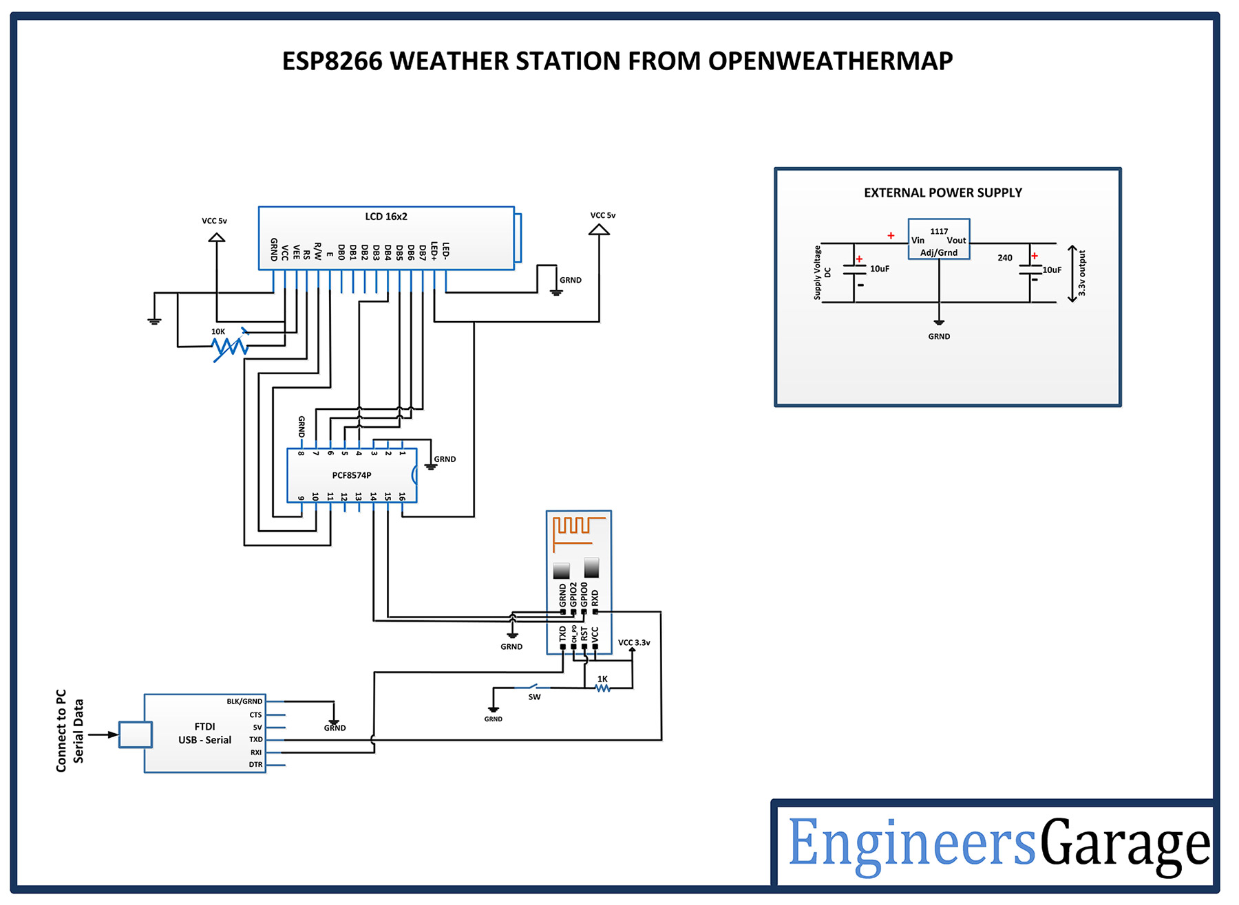 |