In the previous tutorial , we covered how to interface a NEO-6M GPS module with Raspberry Pi (RPi). The module communicates with RPi via the Universal Asynchronous Receiver/Transmitter or UART Protocol .
UART is the most common point-to-point data communication protocol. But it is not the only serial communication protocol. In embedded electronics, I2C and SPI protocols are also widely used for serial data communication. Unlike UART, I2C and SPI are master-slave synchronous serial data standards.
In this tutorial, we will discuss the basics of the I2C protocol.
What is an I2C?
An interintegrated circuit (I2C) or two-wire interface (TWI) is a synchronous serial protocol originally developed by Philips Semiconductors (now NXP). It is a multi-master, multi-slave serial bus for low-speed devices that requires only two wires for serial data communication between multiple devices. It can be easily implemented with two digital input/output channels in one device.
An I2C bus has just two wires through which hundreds of devices can communicate serial data.
As a master-slave communication standard, at least one device connected to the bus must be the master. It is the master device that generates a clock signal for synchronous serial communication.
Slave devices can transfer data to and from the master device(s), which access the slave devices via their I2C addresses. The address of each slave device on an I2C bus must be unique. However, I2C slave devices must still obtain their addresses from NXP.
There are only two wires in I2C where devices can be connected:
1. Serial Data (SDA) – the line over which master and slave devices communicate serial data
2. Serial clock (SCK) – the line through which the master device(s) generates the clock signal.
I2C is a type of half-duplex communication. Note: A master device can only read or write data to the slave at a time. Furthermore, the clock signal and read and write operations are all controlled by the master device(s).
While there can be an unlimited number of master devices connected to the I2C bus, the maximum number of slave devices can be 112 (in 7-bit addressing) or 1008 (in 10-bit addressing).
I2C bus drivers are open-drain, which means devices can pull the I2C signal line down, but cannot pull it up. By default, both lines are raised by pull-up resistors until the bus is accessed by a master device. This is useful to avoid bus contention.
Because master devices can only pull the signal line low, there can be no conflict between multiple masters – such as one master pulling the line low while the other takes it high. If at any time the signal line is low, it means it is accessing a master device.
Therefore, only one master can access the I2C bus at a time. And the bus master can only read or write data with one slave at a time.
Serial data communicated by I2C is divided into 8-bit data packets. The data transfer rate depends on the clock frequency. In default mode, the clock frequency is 100 to 400 kHz.
The clock frequency is:
- 1 MHz in I2C fast mode
- 3.4 MHz in high speed mode
- 5 MHz in ultrafast mode
Advantages of an I2C
UART is the most common serial interface, but it has disadvantages. When using UART, data communication is only possible between two devices. These devices must also agree to a common protocol and have almost the same clock speed.
It is possible to connect more than two devices to UART lines, but this carries a high risk of bus contention. Practically, the maximum data rate achievable with UART is 230,400 bps. And in every 8-bit data transmission, there is an overhead of 2 bits.
It is also not easy to implement UART in software. Viable UART communication requires an external or integrated UART chip.
On the other hand, a serial peripheral interface (SPI) allows only one master device but multiple slave devices. To connect a slave device, four lines are required. For each slave device, an extra line is required for chip selection. Therefore, despite the high data rate (up to 10 Mbps) and full-duplex communication, it is not practical to connect multiple slave devices through one SPI due to the extra lines required for each slave. This limitation is more evident when the entire circuit is arranged on a PCB.
An SPI is typically only good for high-speed, full-duplex data communication from a master device (such as a microcontroller or embedded computer) with a limited number of slave peripherals (say, two or three). However, an SPI is an alternative to UART for high-speed, full-duplex data communication with more than one peripheral device.
Essentially, an I2C represents the best of UART and SPI. Although it allows half-duplex communication, using I2C, an unlimited number of master devices can communicate serial data with hundreds of slave devices over just two wires.
Since master devices can only drive lines low, bus contention is not a concern. Data rates are between those of UART and SPI (up to 5 Mbps), and there is an overhead of only 1 bit (ACK/NACK) for each byte transmitted via the I2C protocol.
An I2C still requires some complex hardware compared to an SPI, but it is not as complex as UART. Furthermore, the software implementation of an I2C is quite feasible.
Furthermore, an I2C is particularly useful when low-speed data communication is required with multiple devices or by multiple masters over just two wires. This is why it is commonly used by embedded sensors and modules. By using an I2C, a microcontroller (like Arduino) or an embedded computer (like Raspberry Pi) can connect and communicate with hundreds of sensors through just two wires, while only connecting its two channels/pins.
Disadvantages of an I2C
An I2C allows serial data communication with multiple devices and multiple masters using just two wires, but it has low data transfer rates and lacks full-duplex capabilities. I2C is simply not an option when full-duplex communication is required or when high data speeds are required.
This means:
- UART is good for basic full-duplex communication between two devices with similar clock speeds.
- An SPI is good for full-duplex, high-speed data communication with two or more peripherals.
- An I2C is good for low speed data communication with multiple devices, between multiple masters on a 2 wire bus.
The I2C hardware
Implementing an I2C requires two open-drain output drivers (open collector in TTL terminology). Both wires on an I2C bus must be pulled up with a suitable resistor. The I2C channels in most sensors and modules successfully communicate serial data over two to three meters of wire.
For data transmission over long distances, dedicated I2C breakout cards are required.
Most microcontrollers and embedded computers have dedicated I2C hardware, which can operate as an I2C master and I2C slave. As an I2C slave it means they also have an I2C address. With I2C hardware, they can generate start and stop conditions, receive an I2C address, and send and receive serial data over the protocol.
If the I2C address is implemented by software, the data bits must be sampled at least twice per clock cycle. Most microcontrollers have sufficient clock frequency that they can easily sample I2C data using an internal timer/counter with or without a prescaler.
I2C voltage levels
Typical voltages used for I2C are +5 and +3.3V. I2C is flexible, however, and can also maintain data communication with devices/interfaces with other voltage levels.
When connecting a higher voltage device to a lower voltage device via I2C, caution is required. Sometimes pulling the I2C bus to a lower voltage device level is enough. But there is still a chance that the higher voltage device will damage the lower voltage device. It is recommended to connect the two devices with different voltage levels on the I2C bus using a suitable I2C level change board.
I2C addresses
Master devices on an I2C bus do not need to have an address, as they generate the clock signal on an SCL line. Slave devices must have unique addresses on an I2C bus.
The I2C addresses of slave devices can be 7 or 10 bits. Some of these devices have fixed addresses, while others have address lines that can be connected to set the device address via an I2C interface.
Since there are a limited number of I2C addresses (only 112 addresses in 7 bits and 1008 addresses in 10 bits), there is a chance that two I2C devices will have the same. More than one I2C device with the same address can be connected to a controller/computer using an I2C hub.
The I2C protocol
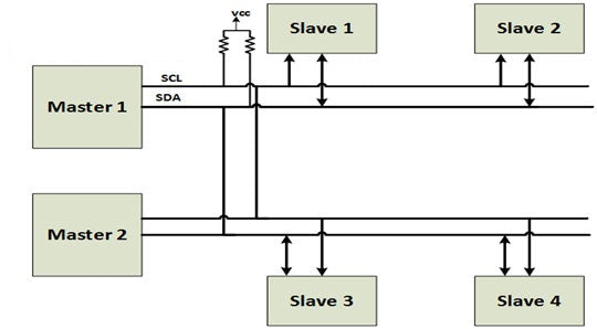
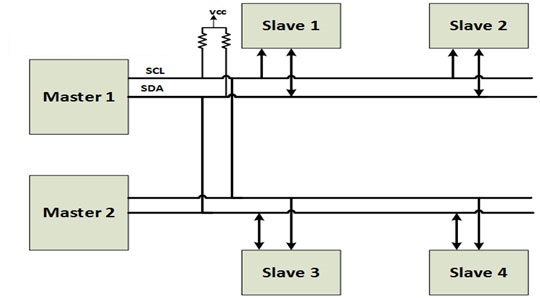
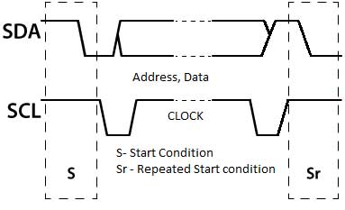
By default, both I2C lines (SDA and SCL) are high. There may be one or more master devices connected to an I2C bus. Data communication is initiated by a master device.
A master device generates an initial condition followed by the address of the slave device. The slave device address must be unique. In 7-bit addressing, bit 0 of the address byte indicates whether the master reads from or writes to the I2C slave. If bit 0 of the address byte is 0, the master device writes data to the I2C slave. If it is 1, the master device reads data from the I2C slave.
After selecting a slave device, data frames consisting of 8-bit data and acknowledgment bits are transferred between the master and slave. There may be repeated initialization conditions for a master to read and write serial data with one or more I2C slaves.
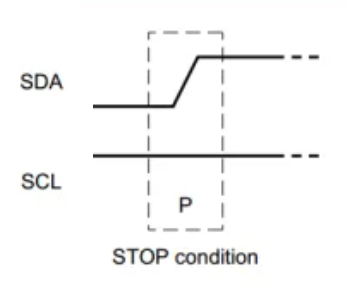
Once data communication is complete, the master device must generate a stop condition to terminate communication over the I2C bus.
The I2C bus can also be used by other master devices. In fact, there can be an unlimited number of master devices connected to an I2C bus as long as the bus capacitance does not exceed 400 pF.
![]()
![]()
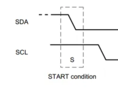
The initial condition
To generate the initial condition, a master device needs to pull an SDA low while leaving the SCL high.
If two master devices attempt to access I2C at the same time, whichever one pulls the SDA down first will gain ownership of the bus. This is called arbitration.
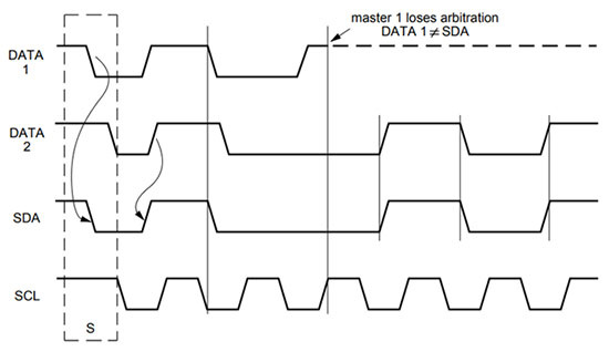
When there is a high to low transition on an SDA line, the I2C slaves are alerted that a transmission is about to begin. Once the bus is controlled by a master, it can read and write data to one or more slave devices, generating repeated starting conditions.
Until the stop condition is generated by the current master bus, other master devices cannot gain control of the I2C bus.
Address Frames
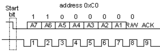
Data is communicated over the I2C bus in 8-bit frames (data packets). The first frame after the initial condition is always an address frame. This frame identifies the slave device with which the I2C bus master must communicate.
In this frame, the 7-bit address of a slave device is transmitted by the master, starting from the MSB of the I2C address. It is followed by an R/W bit, which determines whether the master will read or write data to the slave. If the R/W bit is 0, the master device writes data to the I2C slave. If it is 1, the master device reads data from the I2C slave.
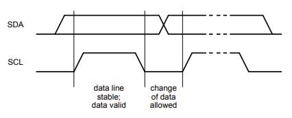
After the start condition, the bus master must pull the SCL line low. Bits are sampled whenever the SCL line goes high. The data (bits) on the SDA line must remain stable when the SCL is high, otherwise it will be interpreted as a repeated start or stop condition. Data bits can only change when the SCL is low. After the initial condition, the SCL is lowered by the master and the data is placed on the SDA line. After that, data is sampled by the slave at each low-to-high transition of the SCL signal.
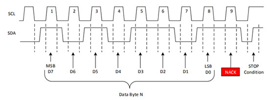
Each 8-bit data frame ends with an ACK/NACK bit. After 8-bit transfer, the receiving device gains control of the SDA line. If the receiving device pulls the SDA line low before the ninth clock pulse, it means it has successfully received the 8-bit data frame.
If this does not occur, it means that the data frame could not be received or the data could not be analyzed according to the I2C protocol. In this case, the receiving device does not pull the SDA line down, but it is up to the master to terminate data communication by generating a stop condition or a repeated start condition.
In the case of an address frame, the receiving device is always a slave device.
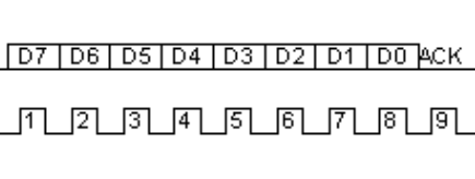
Data frames
After sending an address frame, the bus master will continue sending clock pulses. Depending on the R/W bit, data is read or written by the master device. After each 8-bit frame, the receiving device pulls the SDA line down on the ninth clock pulse.
There can be any number of data frames exchanged between a master and a slave – after the master selects a slave and the read/write operation sends the start signal and then an address frame.
 The stop condition
Once a master gains control of the I2C bus, it can read/write serial data with any number of slaves, generating repeated initialization conditions.
To release the bus, the master must generate a stop condition. The stop condition is generated by pulling the SDA line from high to low while the SCL line is high.
This is why data bits should never change when the clock pulse on the SCL line is high. Otherwise, it will be interpreted as a false stop condition or a repeated false start.
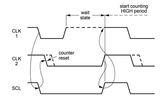
Watch stretching
If a slave device is not ready or unable to process the received data, it may pull the SCL line low to indicate that it needs time to receive/process the data. When the device is ready, it can set the SCL line high, indicating that the master can restart serial communication. This is called clock stretching.
Data bits are always sampled on a low-to-high transition of the clock pulse on an SCL line. Slave devices can only pull the SCL line down after the master releases the I2C bus. When the SCL line is lowered by a slave device, the master devices on the I2C bus avoid generating clock pulses or putting data on an SDA line until the SCL line is cleared by the slave.
10-bit I2C addressing
Advanced I2C devices have 10-bit addresses. They can be used with 7-bit address devices as the address frame for 10-bit devices always starts with the 5-bit sequence, 11110.
This string indicates a 10-bit address of the master device. To select an I2C slave with a 10-bit address, the master device must send two address frames to write data to the slave, or three address frames to read data from the slave.
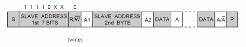
When the master needs to write data to a 10-bit address slave, it must send two address frames. The first address frame contains the 5-bit sequence 11110, followed by two slave address bits and the R/W bit. The R/W bit must be 0 in this case.
After sending the first frame, it must wait for the ACK on the ninth clock pulse. If the acknowledgment bit (an SCL line pulled down by the receiving device) is successfully detected by the master, it sends the remaining 8 bits of the slave address in the next frame.
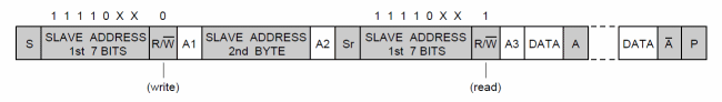
When a master needs to read data from a 10-bit address slave, the R/W bit in the first address frame is still 0, but the second address frame is followed by a repeated start condition.
After the start condition is repeated, the first address frame is sent back to the slave with the R/W bit set to 1.
Advanced I2C protocol
Most I2C devices have 7-bit addresses and use standard mode where the data transfer rate is 100 Kbps. Advanced I2C devices operate in fast, high-speed, or ultrafast mode and typically have 10-bit addresses.
Fast mode I2C devices are backwards compatible and can also work with slower I2C controllers. High-speed I2C devices use two clock states, SCLH and SCLL, and have surge suppression circuitry on both lines of the I2C bus.
High-speed devices do not use clock stretching or arbitration because they have improved line output drivers.
In the next tutorial, we will discuss synchronous serial communication when using the I2C protocol on Raspberry Pi.