In the previous tutorial , we learned how to interface a SIM900 GSM-GPRS modem with Raspberry Pi (RPi) and a desktop computer. We employ UART serial communication to “talk” to the SIM900 modem. Using bidirectional data communication with the modem via a standard UART interface we were able to make/receive calls and send/receive SMS messages on the RPi and a desktop computer.
Using the same UART interface and protocol in this tutorial, we will interface a global positioning system (GSP) module with RPi.
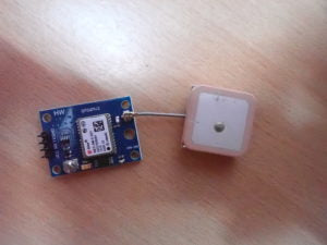
We use the GPS module, NEO-6MV2. This is a low-cost GPS receiver commonly used in embedded devices and robotic projects (there are others from several different vendors). A GPS receiver provides your location by connecting to available GPS satellites.
A GPS receiver can be used to track a location. For example, by connecting a GPS receiver (like the NEO-6) and a GSM modem (like the SIM900) to an onboard controller or computer, we can design a vehicle tracking system. In this system, the GPS receiver obtains the current location of the vehicle and the GSM-GPRS modem communicates this location to a remote server via a mobile network.
Similarly, we can use a GPS receiver on a drone to track its location and manage a GPS-guided flight. The same GPS receivers are used in smartphones, tablets and GPS navigation systems.
Now, let's learn how to interface a GPS receiver with an embedded computer like the Raspberry Pi.
The NEO-6MV2 GPS module
The NEO-6MV2 is a standalone GPS receiver used for navigation. The GPS receiver connects to GPS satellites to obtain its own location. It then outputs the latitude and longitude of your position as serial data.
The NEO-6 module is based on a 50-channel Ublox-6 positioning engine that has a time to first fix (TTFF) of one second. This GPS engine has two million correlators and is capable of performing massive parallel time/frequency space searches. This allows you to find satellites instantly. The module also has a small form factor that makes it ideal for battery-operated mobile devices.

The NEO-6M GPS modem operates with a supply voltage of 2.7 to 3.6V. Communicates GPS data according to the NMEA or UBX protocol. While NMEA is a standard ASCII protocol, UBX is u-blox's proprietary binary protocol.
The receiving chipset has UART, USB, SPI and DDC (I2C compatible) interfaces to communicate this data. The chipset has three configuration pins. One of these configuration pins — CFG-GPS0 — is used to enable the power mode boot configuration.

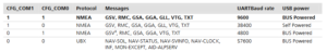
The other two configuration pins — CFG_COM0 and CFG_COM1 — are used to decide whether GPS data is communicated using the NMEA protocol or the UBX protocol.
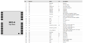
The NEO-6 modem has this pin assignment:
In the module used here, the NEO-6 modem is preconfigured to send data using the serial interface (UART) and encode GPS data to the NMEA protocol.
The CFG_COM0 and CFG_COM1 configuration pins are set to HIGH and as a result, GPS data is communicated via the NMEA protocol at a baud rate of 9600 bps. As you can see in the table above, with this configuration, NMEA data includes GSV, RMC, GSA, GGA, GLL, and VTG messages.
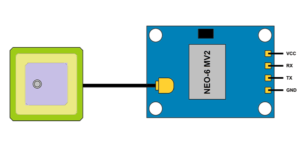
The module exposes only four channels as shown in this pin diagram:
 The module has the following pin assignment:
The module's maximum navigation update rate is 5 Hz. Therefore, an onboard controller or computer can read GPS data from the modem in at least 0.2 seconds.
When the modem is powered on, it takes 32 seconds for a cold boot, 23 seconds for a warm boot, or one second for a warm boot. Because the module is configured for cold start, it initially takes 32 seconds to obtain the GPS reading for the first time.
The module also comes with an external antenna with a sensitivity of -160dBm. The module has an integrated EEPROM and RTC with battery backup. The NEO-6M modem can operate in temperatures between -40˚ to 85˚ C.
Interface with the NEO-6MV2 GPS module
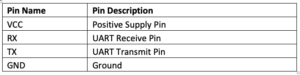
The module has all hardware connections integrated with the NEO-6M modem, which is already pre-configured. According to the hardware configuration, the module exposes only four modem channels:
1. The VCC (modem pin 23)
2. The UART receiver (modem pin 21)
3. The UART transmitter (modem pin 20)
4. Ground (which can be pin 10, 12, 13 or 24 of the modem)
The NEO-6MV2 GPS module can easily interface with the TTL serial port of a controller/computer. However, the VCC pin must be powered with a maximum voltage of 3.6V DC and the ground pin must be connected to a common ground. The module's TX pin must be connected to the Rxd of the controller/computer's TTL serial port.
To connect the module to desktop computers, the USB serial board can be used. Remember that the GPS module has a maximum operating voltage of 3.6V. Therefore, when connected to a controller (like Arduino) or an embedded computer (like RPi), the modem must be powered with VCC from a 3V3 power output pin.
When connected to desktop computers via a USB serial card, this card must first be configured to use 3V3 TTL voltage levels by placing the jumper on the 3.3V connector.
NMEA protocol
NMEA is an acronym for National Marine Electronics Association. In the context of a GPS, NMEA is a standard data format supported by all GPS manufacturers. It is a protocol for GPS data used by GPS receivers and associated software.
NMEA-formatted GPS data can be transmitted over a variety of data communications standards, including UART, SPI, I2C, USB, Wi-Fi, UHF, and Bluetooth.
In the NMEA protocol, GPS data is communicated as sequences of NMEA messages. There are also GPS receivers with different capabilities. Depending on their capabilities, they typically communicate a subset of NMEA message chains. All NMEA messages begin with the character $, followed by the message ID and several data fields separated by commas. The message ends with an asterisk
, followed by the checksum character. Lastly, a carriage return and line feed serve as ending characters.
The GPS module used here communicates GSV, RMC, GSA, GGA, GLL and VTG NMEA messages. Let's examine the NMEA message sequences one by one. GPRMC –
indicates position, speed and time. It has this format:
$GPRMC,hhmmss:ss,Status,Latitude,N,Longitude,E,SOG,COG,ddmmyy,MV,MVE,Mode*CS
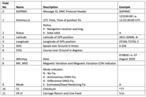
The data fields of the GPRMC NMEA message are described in this table: GPVTG –
indicates the track is in good condition and speed in relation to the ground. It has this format:
$GPVTG,cogt,T,cogm,M,sog,N,kph,K,mode*cs
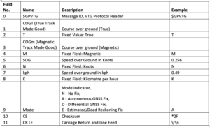
The data fields of the GPVTG NMEA message are described in this table: GPGA –
indicates the time, position and data related to the correction. It has this format:
$GPGGA,hhmmss:ss,Latitude,N,Longitude,E,FS,NoSV,HDOP,msl,m,Altref,m,DiffAge,DiffStation*cs
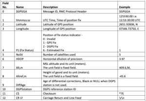
The data fields of the GPGGA NMEA message are described in this table: GPGSA –
indicates GPS DOP and active satellites. It has this format:
$GPGSA,Smode,FS{,sv},PDOP,HDOP,VDOP*cs
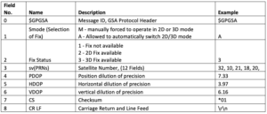
The data fields of the GPGSA NMEA message are described in this table: GPGSV –
indicates the number of SVs in sight, PRN numbers, elevations, azimuths, and SNR values. It has this format:
$GPGSV,NoMessages,MessageNumber,NoSV,PRN,Elevation,Azimuth,SNR,
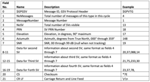
The GPGSV NMEA message data fields are described in this table: GPGLL –
indicates the position data such as the fixed position, the fixed position time and its status. It has this format:
$GPGLL,Latitude,DirLat,Longitude,DirLongitude,hhmmss:ss,A,cs
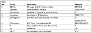
The GPGLL NMEA message data fields are described in this table:
NEO-6MV2 GPS Interface with RPi
To interface the NEO-6MV2 GPS module with Raspberry Pi, power the module VCC from the RPi's 3.3V pin (board pin 1 or 17), then ground from either of the ground pins on the RPi (board pin 6, 9, 14, 20, 25, 30, 34 or 39).
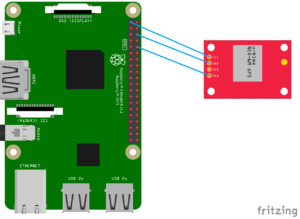
Then, connect the module's TX to the Raspberry Pi's UART Rxd (pin 10 on the board). There is no need to send any serial data to the NEO-6 modem, which means there is no need to connect to the module's RX.
Checking if the NEO-6MV2 GPS module is working
When the GPS module receives power, it initially takes some time to get ready. This will depend on the configuration of the module, whether it is configured for cold, warm or warm start.
After waking up, if GPS satellites are visible to the receiver and it begins to target your location, a status LED on the module will begin flashing.
If this LED does not flash, the module is not working properly or the satellite is not clear. In this case, you can try to get raw GPS data from the module. If you can get at least some information (like UTC time) but can't get location data, it means the module is fine, but there is no satellite visible to the GPS receiver.
Wait for some time (say a few minutes or half an hour) and try to get raw GPS data again. If the module is working properly, it can obtain the location data after some time.
Getting raw data from GPS NEO-6MV2 using Python Raw GPS data can be read from the GPS NEO-6M module using the serial.read or serial.readline methods of Phyton
.
- See how:
- Import the serial, time and sys libraries.
- Open serial the TTL port where the GPS module interfaces using the serial.Serial method.
- This port name will be /dev/serial0. Alternatively, /dev/ttyAMA0 or /dev/ttyS0 can be used as the port name, depending on the primary UART on the respective Raspberry Pi model.
- Read serial data from the GPS module line by line using the serial.readline method. Or use the specific number of characters from the GPS module's serial data using the serial.read method.
Continue reading the data until the NMEA message sequences begin to repeat.
Here is an example Python script that reads the raw GPS data from the NEO-6M GPS module:
import series
of time matter sleep
import system
ser = serial.Serial (“/dev/ttyS0”)
to try:
while True:
received_data = (str)(ser.readline ) #read received NMEA string
print(received_data, “\n”)
except KeyboardInterrupt:
sys.exit(0)
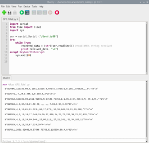
When running the above script on the Raspberry Pi, we receive the following GPS data in the IDLE console:
Getting GPS position from NEO-6MV2 GPS using Python
Raw GPS data contains RMS, VTG, GGA, GSA, GSV, and GLL NMEA message strings. There are a total of nine sequences of raw GPS data messages at a time.
To obtain the GPS location, we can extract the $GPGGA or $GPGLL message strings. Both strings contain the location information. Here we extract the GPS location from the $GPGGA message string.
The raw GPS data can be stored in a string variable. Using string manipulation functions like find , we can search for $GPGGA or $GPGLL in the received string.
If the received GPS data contains one of these strings, split the message string after $GPGGA or $GPGLL using the split function. Then split the data fields of the received NMEA message into an array using the comma as the delimiter in the split function.
Now, you have the $GPGGA data fields or the $GPGLL NMEA message string in an array. You can extract the UTC time, latitude and longitude by accessing a different index of the resulting array. Latitude and longitude can be converted to degrees using simple mathematical operations and formatting on the received values. The converted latitude and longitude values can also be printed to the console or transferred to a variable.
The following is an example of a Python script that extracts the GPS location from the raw GPS data of the NEO-6M GPS module:
import series
of time matter sleep
import system
ser = serial.Serial (“/dev/ttyS0”)
gpgga_info = “$GPGGA,”
GPGGA_buffer = 0
NMEA_buff = 0
def convert_to_degrees(ravo_value):
decimal_value = gross_value/100.00
degrees = int(decimal_value)
mm_mmmm = (decimal_value – int(decimal_value))/0.6
position = degrees + mm_mmmm
position = “%.4f” %(position)
return position
to try:
while True:
received_data = (str)(ser.readline ) #read received NMEA string
GPGGA_data_available=received_data.find(gpgga_info) #checks the GPGGA NMEA string
if (GPGGA_data_available>0):
GPGGA_buffer = received_data.split(“$GPGGA,”,1)(1) #stores data that comes after “$GPGGA,” string
NMEA_buff = (GPGGA_buffer.split(','))
nmea_time=
nmea_latitude=
nmea_longitude=
nmea_time = NMEA_buff(0) #extract time from GPGGA string
nmea_latitude = NMEA_buff(1) #extract latitude from GPGGA string
nmea_longitude = NMEA_buff(3) #extract longitude from GPGGA string
print(“NMEA Time: “, nmea_time,'\n')
lat = (float)(nmea_latitude)
lat = convert_to_degrees(lat)
long = (float)(nmea_longitude)
longi = convert_to_degrees(longi)
print (“Latitude NMEA:”, lat,”Longitude NMEA:”, longi,'\n')
except KeyboardInterrupt:
sys.exit(0)
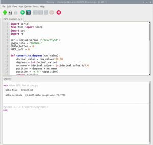
When running the above script on the RPi, we receive the following GPS location in the IDLE console:
GPS position on Google Maps using Python
To show GPS position on Google Maps, Python browser library can be used. You can use this library's open method to open a Google Maps link with the latitude and longitude obtained in the previous example.
Here is an example Python script that shows the GPS location of the NEO-6M GPS module on Google Maps:
import series
of time matter sleep
import system
import web browser
ser = serial.Serial (“/dev/ttyS0”)
gpgga_info = “$GPGGA,”
GPGGA_buffer = 0
NMEA_buff = 0
GPGGA_data_available = “”
def convert_to_degrees(ravo_value):
decimal_value = gross_value/100.00
degrees = int(decimal_value)
mm_mmmm = (decimal_value – int(decimal_value))/0.6
position = degrees + mm_mmmm
position = “%.4f” %(position)
return position
received_data = (str)(ser.read(200)) #read received NMEA string
GPGGA_data_available=received_data.find(gpgga_info) #checks the GPGGA NMEA string
if (GPGGA_data_available>0):
GPGGA_buffer = received_data.split(“$GPGGA,”,1)(1) #stores data that comes after “$GPGGA,” string
NMEA_buff = (GPGGA_buffer.split(','))
nmea_time=
nmea_latitude=
nmea_longitude=
nmea_time = NMEA_buff(0) #extract time from GPGGA string
nmea_latitude = NMEA_buff(1) #extract latitude from GPGGA string
nmea_longitude = NMEA_buff(3)
print(“NMEA Time: “, nmea_time,'\n')
lat = (float)(nmea_latitude)
lat = convert_to_degrees(lat)
long = (float)(nmea_longitude)
longi = convert_to_degrees(longi)
print (“Latitude NMEA:”, lat,”Longitude NMEA:”, longi,'\n')
map_link = '+ lat + ',' + longi
webbrowser.open(map_link)
sys.exit(0)
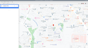
When running the above script on the RPi, we received the following GPS location on Google Maps:
In the next tutorial, we will cover serial communication using I2C on Raspberry Pi.