ESP8266, a System-on-Chip (SoC) manufactured by ESpressif, is the most popular IoT development platform and is a complete and independent Wi-Fi networking solution. The SoC consists of a 32-bit Tensilica L106 microcontroller and a Wi-Fi transceiver. Therefore, the chip can be used to self-host an IoT or embedded application or offload Wi-Fi networking functions to another microcontroller or single-board computer . There are many development boards based on ESP8266. All of these boards have the ESP8266 SoC chip at their heart. These development boards can be used as just a Wi-Fi adapter or as a single-board microcontroller with Wi-Fi networking capabilities.
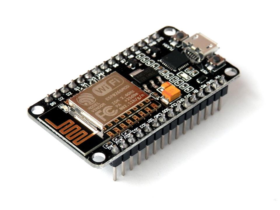
ESP8266 development board example
The on-chip microcontroller itself provides 17 GPIO (general purpose input/output) and a 10-bit ADC analog input. The SoC has four software-only PWM interfaces. The chip is enabled with an SPI interface, an I2C interface, two UART interfaces and an IR remote control interface for serial data communication. Therefore, a carefully selected ESP8266 development board has everything that any capable single-board microcontroller should have. The additional Wi-Fi networking capability allows an ESP8266-based development board to connect to a Wi-Fi network, connect to the Internet, host a web server, and deploy complete Wi-Fi-enabled IoT applications.
When self-hosting an embedded/IoT application, the SoC requires an external flash to boot it directly. When used as a Wi-Fi adapter, the chip can be connected to a single-board microcontroller or a single-board computer using SPI, I2C or UART.
The ESP8266 SoC is designed for ultra-low power technology. It was designed considering applications in wearable electronics, mobile devices and the Internet of Things. The chip can operate in three modes – active, sleep and deep sleep. In deep sleep mode, the chip consumes just 60 uA, and in sleep mode it consumes less than 1.0 mA and 0.5 mA while remaining connected to a Wi-Fi access point. The SoC has a time clock built-in real timer and a watchdog timer, which remain active in sleep mode. The built-in RTC can be programmed to activate the ESP8266 at any required interval or when a specific condition is detected. This way, an ESP8266-based device can be programmed to remain in low-power standby mode until Wi-Fi is needed.
ESP8266, a low-power WiFi-enabled microcontroller solution, is perfect for designing battery-powered wearable electronics and portable/mobile IoT devices.
ESP8266 Features
Some of the most notable features of the ESP8266 SoC are as follows.
- 11 b/g/n
- 2.4 GHz Wi-Fi with WPA/WPA2 security
- Wi-Fi Direct (P2P station), SoftAP, SoftAP+ station
- Integrated TCP-IP protocol stack
- Supports IPv4, TCP/UDP/HTTP/FTP network protocols
- Antenna diversity (external, PCB trace, ceramic chip, IPEX connector)
- Supports STA/AP/STA+AP operating modes
- GPIO, SDIO 2.0, SPI, I2C, UART, I2S, IR remote control, PWM
- Integrated 10-bit ADC
- Integrated TR switch, balun, LNA, power amplifier and corresponding network
- Integrated power regulator, PLL and power management units
- Supports smart link for Android and iOS devices
- Configurable via AT instruction set, Cloud Server, Android and iOS apps
- Cloud server development support as well as SDK for custom firmware development
- The firmware can be updated via UART download and also OTA (via Wi-Fi network)
- Supports WEP/TKIP/AES encryption
- 32-bit Low Power Integrated Microcontroller
- Low power consumption, less than 10uA in deep sleep and empty hotspot
- Wake up and transmit packets in less than 2 ms
- Wide operating temperature range -40˚C to 125˚C
ESP8266 Modules
There are several modules based on ESP8266. These are either standalone modules or complete development boards. Standalone modules typically contain only the ESP8266 SoC and the components needed to run it. Most standalone modules are available as ESP-NN series (ESP01 to ESP14) from the supplier AI-Thinkers. An independent ESP-WROOM-02 module is available from Espressif itself. Other independent modules are available from other suppliers, such as Wireless-tag, Olimex, Smarttime and Qilianer. The following table lists and compares the available standalone ESP8266 modules.
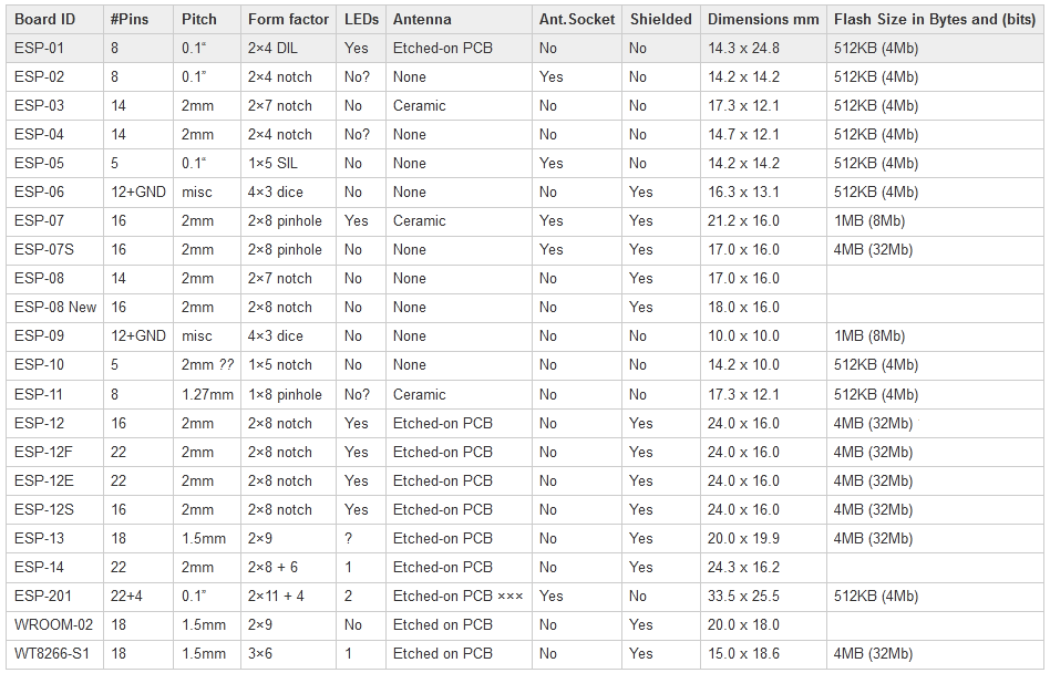
These independent modules serve only as a Wi-Fi adapter or a Wi-Fi-enabled microcontroller development board. These modules vary in size, broken pins, exposed features on the chip, antenna type, and flash memory. A basic ESP8266 SoC requires an external flash memory, reset and program circuitry, chip enable circuitry, 3.3 voltage regulator power supply, and a USB to serial adapter. All of these required features can be integrated into a module or some can be provided externally.
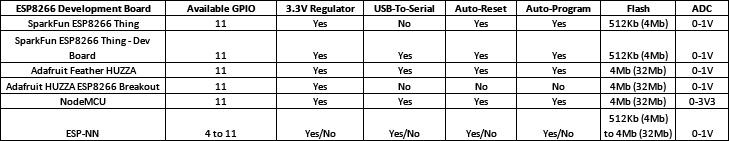
ESP8266 based development boards have all the necessary circuitry with or without USB interface for programming. Some popular ESP8266 development boards are available from Adafruit, SparkFun, NodeMCU, and AI Thinkers. The following tables list notable features of some of these ESP8266 development boards.
ESP8266 development boards can be divided into two categories:
- ESP8266 Development Boards with USB Interface : These development boards have a USB interface for programming. They have all the necessary circuitry built in and do not require any external circuit configuration. Some examples of such development boards include SparkFun ESP8266 Thing, Adafruit Feather HUZZA, SparkFun Blynk Board, and some of the AI Thinker ESP-NN boards. When these cards are connected to a desktop computer via USB cable, they appear in the device manager on a Windows PC or in lsusb on a Linux system. They have an integrated 3.3 V regulator and can be programmed directly via a USB interface. These development boards do not require any external circuitry for configuration and operation. At most, it may be necessary to solder the header pins or leave the header already soldered.
- ESP8266 development boards without USB interface : These development boards require a USB to serial adapter for programming. The board may have a 3.3V regulator or not at all. In addition to the 3.3V regulator and USB to serial adapter, the board requires external circuitry to enable the chip and add a reset and programming button.
The USB to serial converter must operate at 3.3V. If the USB to serial adapter operates at 5V, it will damage the ESP8266 development board. The most popular USB to serial adapter used with ESP8266 development boards is the FTDI FT232RL as it can be switched between 5V and 3V3 operation.
To connect the USB to serial adapter with the ESP8266 development board, connect the ground, RX pin, TX pin, and DTR pin (if available) of the USB to serial adapter to the ground, TX, RX, and DTR pins of the ESP8266 Chip .
If the ESP8266 development board does not have a built-in 3.3V regulator, 3.3V power can be supplied via the Arduino's 3.3V output or using LM1117-3.3. The 3.3V output of most Arduino boards is not powerful enough to drive an ESP development board. Therefore, it is better to supply power via LM1117-3.3. The LM1117-3.3 must be connected as follows to supply power to an ESP8266 board.
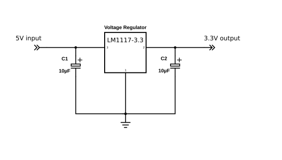
Circuit diagram of LM1117 3.3V voltage regulator for ESP8266 board.
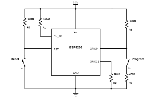
Circuit diagram to reset, enable and program the ESP8266.
To enable the ESP8266 chip, connect the CH_PD (Chip Enable/Chip Power Down) pin to VCC through a 10K resistor. Disable SD card initialization by connecting GPIO15 to ground via a 10K resistor. Select normal boot mode by connecting GPIO0 to VCC via a 10K resistor. To avoid random reset, connect the RST pin to VCC through the 10K resistor. GPIO2 must remain disconnected. Connect a button between the RST pin and ground to add a reset button. Connect GPIO0 to ground via the 470Ω resistor to add a program button. GPIO0 must be reduced when programming the ESP8266. The chip enable, reset and programming circuit for the ESP8266 development board is shown below.
Programming ESP8266 development boards
Programming the ESP8266 development board requires loading firmware onto it. There are mainly three methods for programming ESP8266 development boards. There is not one, but several ways in which the ESP8266 development board can be programmed.
- Using Arduino IDE – Arduino provides a third-party plugin to use Arduino IDE for different CPUs. It uses the Xtensa GCC toolchain, available on Github as esp8266/Arduino. It also provides ESPTool to upload hex files (application sketches/codes) to the ESP8266 SoC. After the board manager URL is added to the IDE's preferences configuration menu and the ESP8266 board is installed from Tools->Boards->Board Manager, the ESP8266 development board code can be written, edited, compiled and loaded from the Arduino IDE. as is done for Arduino boards.
- Configure the GCC toolchain and SDK manually: An open source toolchain for ESP8266 development boards is available on Github. This toolset can be used to create a custom firmware file for you. The toolchain runs only on a Linux host or can run on other desktop systems using a Linux virtual machine.
- Using pre-built custom toolsets: Some pre-built custom toolsets are available and can be directly downloaded as ESP8266 firmware and then sketches (application codes) can be flashed to ESP8266 for that firmware. Some of the popular tools for ESP8266 development boards are as follows –
- Espressif firmware source
- Electrodragon ESP8266 AT Command Firmware
- Espressif AT controller firmware
- NodeMCU firmware for running LUA scripts on ESP8266
- MicroPython firmware, for running Python 3 scripts on the ESP8266 and various other microcontrollers
- Modifiable SDK to run 2020 standard Javascript on ESP8266, ESP32 and some other microcontrollers
- ESP8266Basic, a basic interpreter for browser-based development on the ESP8266
ESP8266 Applications
ESP8266 is a powerful Wi-Fi networking solution with single-board microcontroller capabilities. It is best suited for mobile, wearable, and IoT devices. There are several ESP8266 development boards available and they can be programmed using different sets of tools. Different sets of tools allow you to program ESP8266 development boards in various programming languages, such as C, Python, Javascript, LUA script, and AT commands. Some of the possible IoT applications using ESP8266 development boards are home automation, mesh networking, IP cameras, baby monitors, wearable electronics, industrial wireless control, security identification tags, sensor networks, Wi-Fi location-aware devices. Fi, Wi-Fi headlight position system, smart plug and lights, Internet controlled home appliances, etc.
Design Considerations with ESP8266
There are some factors that should be considered before selecting ESP8266 development boards for WiFi-enabled IoT applications –
- ESP8266 operates at 3.3V, even a 5V supply can kill the SoC. The ESP8266's GPIO can only supply or absorb 12 mA per output pin. Therefore, the ESP8266 is only suitable for low-power IoT applications.
- The voltage range of ESP8266's analog to digital converter is only 0~1V. This limits the use of ESP8266 in the field of analog detection.
- The ESP8266 shares CPU time and system resources with the Wi-Fi transceiver. Therefore, the application code should not have long loops that never complete execution. Therefore, the ESP8266 should be used for specific IoT applications.
- The PWM and I2C in the ESP8266 are emulated in software. There is no dedicated hardware for them.