The Arduino force-sensitive resistor is a new member of the traditional Arduino resistive sensor family. Resistive sensors respond to any change in physical quantity by varying their resistance. A fixed voltage is applied to the sensor when the resistance changing voltage drops. This voltage drop can be sampled and the change in physical quantity can be measured.
Generally, in a resistive sensor, copper or some other material (conductor) is etched onto the board in concentric circles, parallel twisted single line, or rectangular orientation. The conductive line is divided into two halves, dividing it in half. Voltage is applied to half of the conductor and the other half remains open.
When the conductor is exposed to a physical quantity (physically touched, etc.) and a passage is created between the two halves, voltage begins to flow from one half to the other. The voltage value depends on the line width of the conductor or the area/thickness of the undervoltage path of the conductor.
Popular Arduino resistive sensors are rainwater and soil moisture sensors. Both work on the same principle. The rainwater sensor has a conductive line. The soil moisture sensor has two legs made of conductive material.
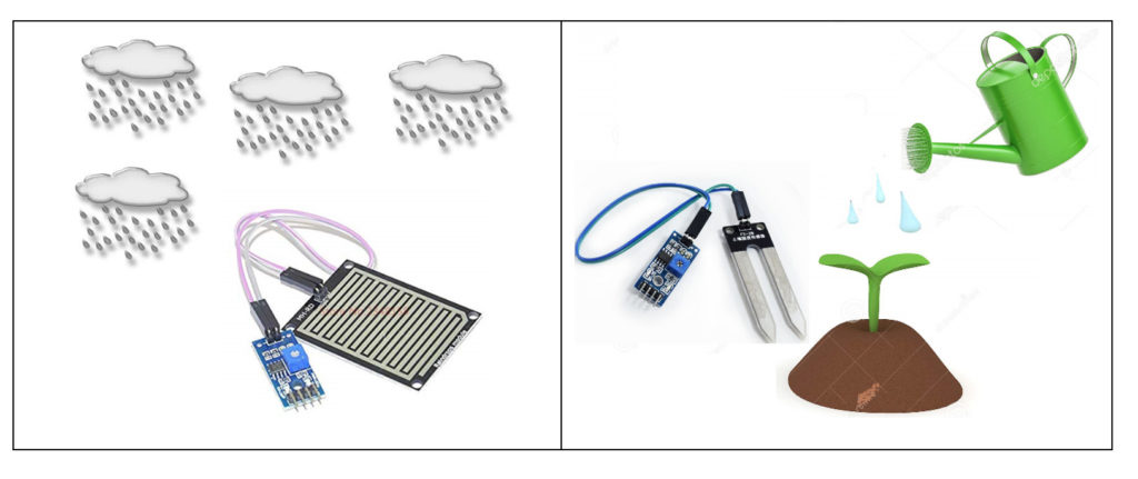
The water tank level sensor is the best example of resistive sensors. Two copper wires are lowered into a tank. Through one wire, voltage is applied, and the other is open. When the water reaches the path of the two wires, voltage begins to flow from one wire to the other. Knowing the depth and volume of the tank water quantity equation can be easily derived.
Disadvantages of resistive sensors?
- They lack precision (even between sensors).
- They are bulky and consume a lot of energy.
- The conductor on the sensor board corrodes very quickly.
The biggest advantage is that they are cheap and can even be made at home.
Force Sensitive Resistor
A force sensitive resistor (FSR) is a new member of resistive sensors. It can measure the force applied to it. The sensor is an improved version of its predecessors. FSR is more flexible, accurate, drains less energy and does not corrode quickly.
As?
The conductive material is glued to a flexible membrane. The membrane is sandwiched between two semiconductor substrates. The substrates are separated from the membrane. Each printing path is created between the membrane and the semiconductor. At launch, the path breaks. Just like the touchscreen, the conductive material is encased in an airtight plastic casing. Only the pins are exposed to the external environment.
The conductive material in the sensor does not lose electrical characteristics and therefore accurate measurements can be carried out over a long period of time.

How does FSR work?
The FSR works in the same way as other resistive sensors. The FSR just maintains the same total resistance parameter throughout its life. Its total resistance does not degrade; Furthermore, the change in resistance during measurement is accurate.
FSR is like a variable resistor in the circuit. Suppose we connect a fixed resistor in series with the FSR and measure the voltage drop/gain across the fixed resistor. We can easily interpret the value of resistance change in FSR. The resistance change in FSR is due to the applied external pressure.
The circuit will act as a voltage divider. FSR, a fixed resistor resistance, is known. The applied voltage is also known. We can easily calculate the voltage across the fixed resistor using the voltage divider formula.

LED Bar Chart with Arduino and FSR (Force Sensitive Resistor)
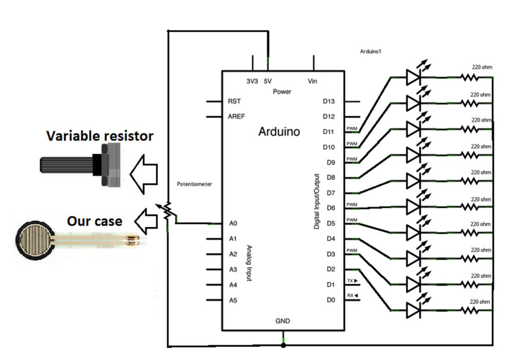
Let's play with the LED bar chart example. I modified the original example (circuit and code) available on the Arduino platform. In the original example, instead of the FSR, a potentiometer is used and there is no concept of a voltage divider. Also, the LEDs are powered by GPIOs in the original example, which is not a good idea, especially when you have a lot of power-hungry LEDs in the circuit.
I decided to power all the LEDs from an external power supply. You can use the 5V output of the Arduino's built-in regulator to power LEDs. Built-in regulators can manage power easily. Keep in mind that all LEDs cannot be turned on at the same time. They will drain all power and probably restart the Arduino. I advise you to power your Arduino via a 12 volt power pulley. Avoid USB power from PC.

The output of the force sensitive resistor is connected to the analog pins 0 of the Arduino, the 10k resistor is used in series with the FSR.
Important: Arduino operates with 5 volts, so the input to an Arduino analog pin 0 must not increase 5 volts. Carefully select a fixed resistor resistance depending on the FSR resistance. The voltage across the fixed resistor must not increase by 5 volts.
In the original case (diagram below), the LEDs are powered by GPIOs, without a voltage divider, instead of a variable resistor.
Project code
The LEDs will light depending on the pressure applied to the FSR. The voltage across the fixed resistor can be seen on the Arduino serial monitor.
First, I declared the Arduino analog pin. Next, an array is defined that contains the reference numbers of the GPIOs LEDs on the Arduino. In configuration, serial communication is enabled at 9600 bits per second and GPIO pins for LEDs are declared as output.
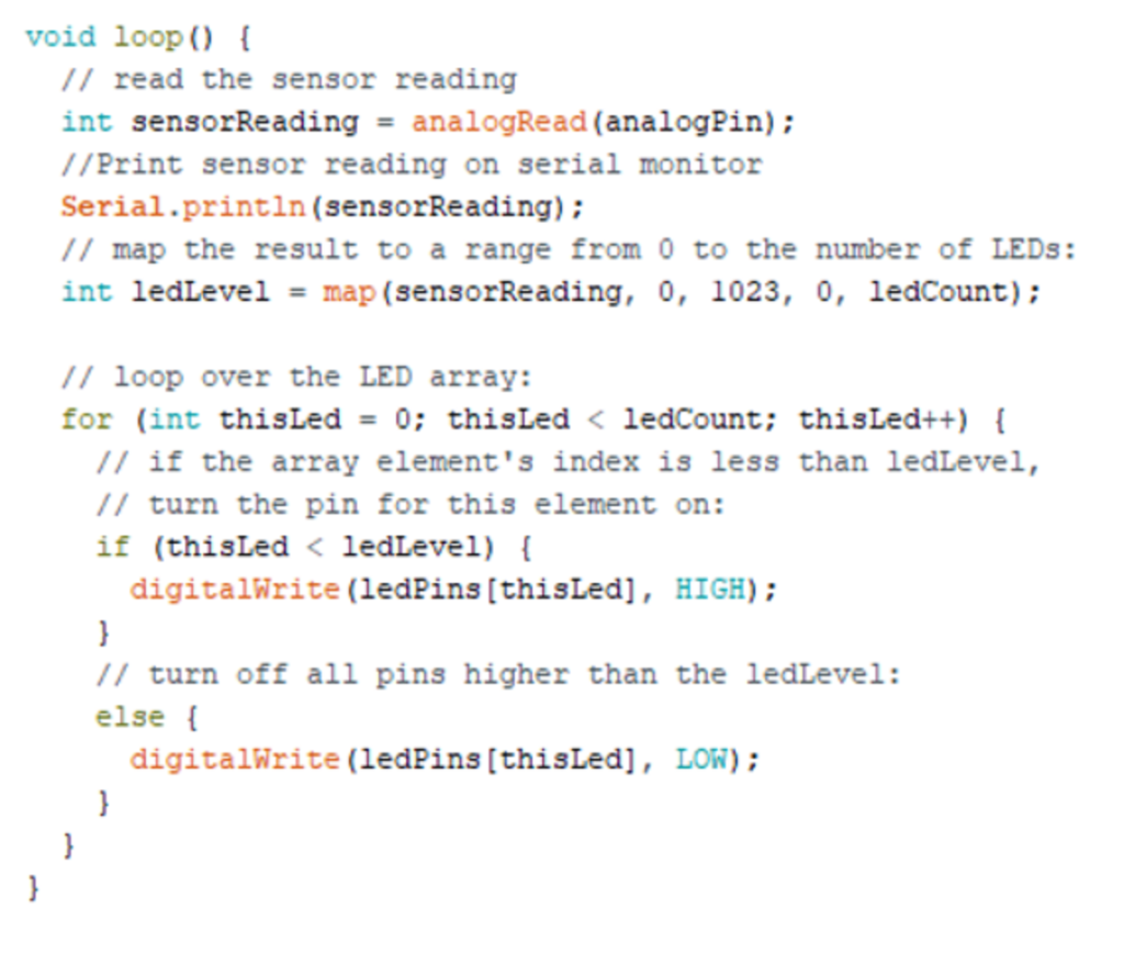
The voltage across the fixed resistor is continuously read and printed on the serial monitor in the loop function. Then the led GPIOs are mapped to specific numbers in the range between 0 and 1023. The range of 0 to 1023 is the ADC resolution (10 bits). In our case, 5 volts on analog pin 0 means the Arduino will read it and give us 1023 representing 5 volts. If 2.5 volts at A0 then Arduino will give us 512. So 10 LEDs are mapped as LED1 (0-101), Led2 (102-204) and LED10 (922-1023).
In the for loop, the LEDs turn on and off. Suppose if the read voltage value is 600, LED1,2,3,4,5,6 will light up. The LEDs will form a pattern if you lightly press the FSR and start increasing the pressure. The launch pattern will be observed in the reverse direction.
Forms
Force-sensitive resistors can be used to measure the force experienced during accidents (installed in vehicles). The voltage variation property of resistor sensors can be used to make a DIY block through which the mouse cursor can be controlled (Matlab Simulink application for cursor control).
Let's DIY the project: Where to buy parts?
Mouser: LEDs
Mouser: Resistors
Mouse: Arduino
Mouser: FSR
Mouser: Breadboard
(tagsToTranslate)Arduino