A Zener diode is one of the types of diode often used in any electronics bench. This is because Zener diodes are almost always used in power supply circuits and wave shaping circuits. Zener diodes are like a normal PN junction diode, although they are heavily doped. This causes the diode to behave differently than a signal diode when operating in the reverse bias region.
Both a signal diode and a Zener diode operate similarly in the forward bias region. In reverse bias, a signal diode blocks any current from the cathode to the anode. Only a negligible amount of reverse current, including reverse saturation current and body current, flows through the diode in a range of nA or uA. This current is so small compared to any circuit current that it cannot drive any load. The circuit current is usually in the mA range. When the reverse voltage is increased beyond a certain voltage called knee voltage, the current through the diode from cathode to anode increases exponentially, soon reaching the current level of the circuit. At this point, a signal diode or power diode is damaged. Signal diodes are usually open-circuited, while power diodes become short-circuited when damaged. Therefore, a signal diode and a power diode always allow current to flow in only one direction, that is, from the anode to the cathode. Any excessive voltage applied to allow current to flow from the cathode to the anode breaks the diode.
A Zener diode is different. It allows current to flow in both directions. However, the reverse current (from the cathode to the anode) can only flow when the reverse voltage is greater than a precise nominal voltage, i.e. the Zener voltage. When a Zener conducts circuit current in the reverse bias condition, it lowers the Zener voltage and allows the resulting circuit current to flow through it.
What is a Zener diode?
A Zener diode is a heavily doped semiconductor diode designed to operate in the reverse direction (cathode to anode). These diodes are designed to have their reverse breakdown at a sharp, well-defined 'reverse voltage' so that they can operate in the reverse bias region without breaking down. The specific voltage at which a Zener diode exhibits reverse breakdown is called 'Zener voltage'. Zener diodes are available with a wide range of Zener voltages, typically from 1.8 V to 200 V. A Zener diode only conducts current in reverse bias when the applied voltage is greater than its Zener voltage.

The electrical symbol of a Zener diode is different from that of a generic diode. A regular diode (signal or power diode) is shown in a circuit using the following symbol.

The following symbol shows a Zener diode.

Note the bent edges of the bar in the Zener diode symbol. It is important to distinguish a Zener diode from a normal diode in a circuit diagram. Regular diodes do not conduct current in response to any reverse voltage and act as an open circuit. A Zener diode conducts from the cathode to the anode if the reverse voltage is greater than its Zener voltage. This fact must always be considered when analyzing a given circuit.
How a Zener Diode Works
A Zener diode is a heavily doped semiconductor diode. A regular semiconductor diode in reverse saturation undergoes Avalanche breakdown when the applied voltage exceeds the knee voltage. Avalanche breakdown in regular diodes breaks them, causing them to open circuit (usually in the case of signal diodes) or short circuit (usually in the case of power diodes).
Zener diodes in reverse saturation exhibit two types of breakdown – Avalanche Breakdown and Zener Breakdown. A Zener diode does not break down in either Zener breakdown or Avalanche breakdown.
When a regular semiconductor diode receives reverse voltage, its depletion region widens due to the effect of the applied electric fields. The width of the depletion region continues to increase as the applied reverse voltage increases. All this time, a small reverse saturation current flows from the cathode to the anode due to the minority charge carriers. At a certain reverse voltage, the 'Knee' voltage, the minority charge carriers have enough kinetic energy due to the electric field in the depletion region that they begin to collide with the stationary ions, eliminating more free electrons. The newly generated free electrons also gain similar kinetic energy due to the electric field across the depletion region. They also collide with stationary ions, eliminating an even greater number of free electrons. This works like a chain reaction by accumulating a large amount of current through the depletion region that the diode becomes conductive. This is called the 'Avalanche' collapse.
A Zener diode has a different type of reverse bias breakdown. This is called the Zener collapse, which occurs even before the Avalanche collapse. A Zener diode is heavily doped. It has a greater number of impurity atoms than a normal diode, therefore, it has a greater number of ions in the depletion region. Due to the greater number of ions, the depletion region of a Zener is very thin. There is a stronger electric field in the depletion region due to its narrow width. Due to the strong electric field in the depletion region, the valence electrons of the ions enter the conduction band and a large amount of current starts flowing from the cathode to the anode.
Note that Avalanche breakdown results from the collision of minority charge carriers with the ions in the depletion region. At the same time, Zener breaking is a quantum phenomenon that occurs because valence electrons moved from the valence band to the conduction band under the influence of the electric field through the narrow depletion region.
The Zener break occurs before the 'Avalanche' break. Avalanche breakdown does not occur at a specific voltage and largely depends on the operating conditions of the diode and circuit. Zener breakdown occurs at a sharp voltage, the Zener voltage, which is predefined by the doping level of the diode. Once a Zener diode goes into Zener collapse, it is conductive from cathode to anode and there is no chance of 'Avalanche' collapse.
As a Zener diode begins to conduct in reverse bias, the voltage drop across it is fixed at the Zener' voltage, which remains unaffected by source voltage variations. However, the current through the Zener can vary depending on the circuit current drawn by the load. Once the charging current stabilizes, the current through the Zener diode also stabilizes.
Zener diodes use both phenomena – Zener breakdown and Avalanche breakdown. If the Zener voltage is up to 6V, it starts conducting reverse bias on the Zener voltage due to Zener breakdown. If the nominal Zener voltage is greater than 6 V, the Zener diode leads to Avalanche breakdown at the nominal voltage. Zener diodes conduct higher current when they conduct due to Avalanche failure than when they conduct due to Zener failure.

When a Zener diode is forward biased, it operates like a normal diode. Due to high doping, the maximum forward current of Zener diode is always higher than that of normal diodes.
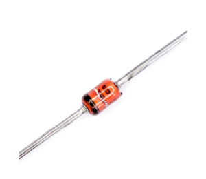
Zener diode packaging
Zener diodes come in through-hole and SMD packages. Through-hole models are generally encapsulated in glass to handle high power dissipation. Both types of packaging have a stripe at one end to indicate the cathode.
Connecting Zener diode in a circuit
In a circuit/network, a Zener diode can be connected with the load in series with the diode or with the load parallel to the diode. The Zener diode is always wired to operate in reverse.
When the Zener is connected in series to the load, the applied voltage drops by the Zener voltage of the diode, and the remaining voltage appears at the anode end of the Zener. There is usually a resistor connected in series with the Zener diode. This resistor and the remaining resistance of the load circuit determine the current through the Zener diode. The same current flows through both the load and the Zener diode.
When Zener is connected with load in parallel, the same voltage applies to the load network until the applied voltage is less than the Zener voltage. As the applied voltage increases beyond the Zener voltage, only the Zener voltage that drops across the diode appears in the load network. Therefore, the voltage in the load network never exceeds the Zener voltage. Now, the current through the load network depends on the Zener voltage and load resistance. If a resistor or other network is already connected in series to the Zener (and the load network) before the voltage source, the current is already limited by that resistor or network.

Zener Diode Reference
There are hundreds of Zener diode models available. The following table lists some of the popular Zener diodes.

Zener diode applications
Please note that this list is not exhaustive. This list is just an attempt to list popular Zener diodes with Zener voltages up to 6V. This table can serve as a starting point for exploring Zener diodes.
The Zener diode has the following common applications:
- Voltage reference: When a load circuit is to be supplied with a fixed voltage, it can be connected in parallel with a Zener diode of the same Zener voltage. This way, the voltage on the device/charging network will appear equal to the Zener voltage, but never higher than that. The Zener voltage source must be greater than the Zener voltage; otherwise the Zener diode will not conduct in the reverse direction and the applied voltage less than the Zener voltage will appear on the load.
 Note that this is not ideal voltage regulation. In the above circuit, the current to the load is limited by the resistance. The voltage to the load may vary depending on the current drawn by the load itself. Voltage can also vary due to temperature.
- Multi-rail power supply – A multi-rail power supply can be designed using multiple Zener diodes. Zeners can be connected in series to provide different voltage drops together. It's the same as using Zener for voltage reference. A single Zener diode is used in a simple voltage reference to provide a fixed voltage drop across a load network. Multiple Zener diodes are used in a multi-rail supply to provide symmetrical and/or rising voltage drops. Remember that the current through the Zener diodes must be sufficient to activate the charging networks. To achieve this, the Zener diodes themselves must have an adequate power rating and there must be no network or resistance limiting the current through the Zener diodes beyond the current levels required in the load. Below is a symmetrical power rail designed with Zener diodes.

Below is another multi-rail power supply circuit using Zener diodes.

- Voltage clamping: AC signals can be clamped using a Zener diode. If the peak amplitude of an AC signal is high Vpeak, a Zener diode of Zener voltage, Vz, can clamp the positive peak at Vz by connecting the output to the cathode of the Zener and connecting the anode of the Zener to ground. The fixed signal level can be increased above Vz by connecting a positive rail with the required increment on the Zener anode instead of connecting it to ground. This will also completely remove the negative cycle from the output.
 Even two Zener diodes can be connected in opposite directions in series to achieve symmetric clamping of the input AC signal.

- Voltage Translation – The Zener diode can be used to smooth the input power of a voltage regulator. By connecting a Zener diode in series with a voltage source to a voltage regulator, the input voltage source can be reduced by Vz. Compared to a voltage drop resistor, the Zener diode instead can tolerate all current variations from the load at the other end of the voltage regulator.
 How to Select a Zener Diode
The two most important factors that determine the selection of a Zener diode for a given application are its 'Zener voltage' and power rating. A Zener diode must be selected by the Zener voltage that must be reduced by its series connection or must supply through a parallel connection. Secondly, its rated power must be sufficient, not limiting the current consumed by the load device or network.