
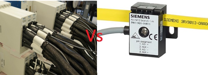
The Actuator Sensor Interface is a standard Fieldbus interface for connecting actuators and binary sensors in a PLC, DCS or PC based automation system. It is the only worldwide standardized bit-oriented Fieldbus. Traditionally, actuators and sensors were connected to a PLC controller or other controller using parallel wiring. The complex array of wires was difficult to install, maintain, and troubleshoot. Parallel wiring was also quite expensive. Then, in the late 1980s and early 1990s, AS-i was developed by Siemens in partnership with ten other companies as a serial interface for low-level actuators and sensors. The interface provides industrial networking to the lowest process level in automation systems.
AS-i simplifies networked sensors and actuators, reducing the network to two wires. The same wires are used to power the input/output devices, i.e. the sensors and actuators. It connects binary sensors and actuators which are simple on/off devices. AS-i networks can be connected to higher level networks such as PROFIBUS, DeviceNet and Industrial Ethernet. The interface allows you to connect 31 or 62 slave devices within a radius of 100 meters. The range can be extended up to 300 meters using repeaters. Fieldbus also allows analog data communication. With a flexible topology, the interface also offers a safety feature called “AS-i Safety at Work”. There is no doubt why this serial interface has become the de facto standard for simple input/output networks in automation.
What is an actuator sensor interface?
The Actuator Sensor Interface is a standard bit-oriented fieldbus that connects binary sensors and actuators at the lowest process level in automation. It connects simple nodes such as buttons, limit switches, process valves, solenoids, relays, indicators and on-off devices with PLC or other controller. The interface allowed the complete replacement of complex cable harnesses with an AS-i cable, which is a simple 2-wire, unshielded, untwisted cable. The cable allows the transfer of standard and security-oriented data on the same line. Furthermore, low power sensors and actuators can be powered by the same cable. In most automation sites, AS-i is now the de facto network solution for the first level of automation due to its simplicity, low cost, flexibility and security features.
Why AS-i?
In industrial automation, low-level sensors and actuators are the majority of devices that must be installed and configured first. These simple command devices make up the majority of the network. Its installation, maintenance and troubleshooting are the most tedious work for automation engineers. If most of the devices are connected to the PLC controller by discrete cables, organizing the mesh will be the most frustrating thing. AS-i not only simplifies cabling, but also provides a standard network protocol for communicating with most I/O devices in the field.
The AS-i interface simplifies cabling in low-level automation and minimizes assembly costs. The field bus can be installed in different topologies such as bus, star, ring, daisy chain, tree, etc. AS-i is flexible and quick to install and configure with fewer components. This is the safest, simplest and fastest connectivity solution in the field.
The only components required to configure Fieldbus are the AS-i master, the AS-i interface and the yellow AS-i cable. There is no need for T-pieces or pre-assembled cables to connect devices. The I/O devices simply need to be screwed onto a single 2-core yellow cable and that's it. The modules (AS-i interfaces) that connect devices to the cable simply pierce the cable's rubber insulation and establish secure contact with each of the cable's two wires via two gold-plated needles respectively. Among all available low-level replacement networks, AS-i is the most economical option with the highest performance and security. There is almost no assembly cost and no chance of installation error. Because it is not twisted, there is no need to strip or terminate the cable.
The same cable enables the communication of standard data and security-oriented data and at the same time also provides power to the devices. AS-i is the only low-level Fieldbus compatible with all other higher-level Fieldbus systems, including PROFIBUS, Industrial Ethernet, PROFINET, DeviceNet, CC-Link, etc. The latest standard even allows for the interfacing of smart sensors like IO-Link. Although AS-i 3.0 allowed connecting only simple command devices (On/Off) to the PLC controller, the latest AS-i 5.0 standard allows communication of larger volumes of data at higher rates.
AS-I standard
The interface was developed by Siemens and a few other companies in the 1990s. Since its inception, AS-i has been developed as an open technology. Soon after its development, a membership-based organization called the AS International Association was formed for standardization and further development of the protocol. The technology complies with the global standard IEC 62026-2:2015 and local standards including EN 50295 (Europe), GB/T18858.2 (China), JIS C 82026-2 (Japan) and KS C IEC 62026-2 (South Korea).
AS-i Components
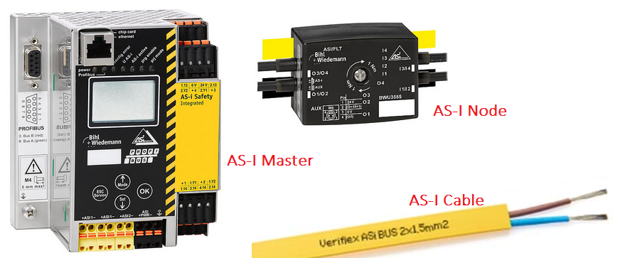
AS-i compatible low-level sensors and actuators are available from hundreds of automation suppliers. There are already millions of AS-i field devices installed and operational around the world. These simple command input/output devices include inductive proximity switches, pushbuttons, process valves, three-phase variable speed motors, keypads, limit switches, indicators, light barriers, and many other on/off devices. Devices can be connected into an automation field in any selectable topology. There are three main components of an AS-i.
- AS-i Master: AS-i field devices connect to a PLC or controller via a master-slave architecture. The AS-i master acts as a gateway for devices to connect to the higher-level controller or control system. The devices operate as slave devices on the network. A single AS-i master can connect up to 62 slave devices to the PLC controller, transferring up to four inputs and four outputs from each device at any time. Digital and analog data can be communicated via cable. The master is responsible for setting line parameters, managing data traffic on the line, running diagnostics, and monitoring slave devices.
- AS-i cable: This is an unshielded, untwisted yellow cable with two cores. The cable has a line impedance of 70~140 ohm. The cable carries data and power to field devices. Sometimes an additional flat black cable is used to supply 24 VDC to the actuators. For special applications, a round cable can also be used. Field devices can be fixed anywhere on the cable as it uses a special drilling technology to connect the modules as mentioned above. The drilling mechanism also ensures no loose connections and eliminates any chance of reverse polarity.
- AS-i nodes: These modules connect sensors and actuators with the AS interface cable. The nodes are designed to penetrate vertically into the profiled cable, establishing a secure connection with the cores via four gold-plated needles.
In addition to the main components, a power supply that provides a constant 30 VDC to the AS-i master and field devices is required. If power is supplied via the AS-i cable only, the power supply acts as a data decoupler separating the data signals and the power supply. For field devices powered by standard 24 V, not even a 30 V DC power supply is required. These devices can draw power from the PLC rack system itself.
Field devices can be connected directly to a PLC controller via the AS Interface master in the PLC rack or connected to a higher-level fieldbus such as PROFIBUS or DeviceNet again via the AS-i master only.
How AS-i works
Field devices are connected to the AS-i in a master-slave configuration. Slave devices are available in two addressing modes – standard AS-i slaves (A slaves) and AS-i slaves with extended addressing mode (A/B slaves). With a single AS-i master, up to 31 standard AS-i slaves can be connected. Since A/B slaves can operate in pairs at the same address, up to 62 AS-i slaves with extended addressing mode can be connected to a single AS-i master.
Each standard AS-i slave can receive 4-bit data and send 4-bit data. Often these bits are used as binary sensors or binary actuators. This means that up to 4 binary sensors and four binary actuators can be connected to each AS-i node that is a standard AS-i slave. Thus, 248 binary attachments (124 inputs and 124 outputs) can be made on the AS-i network with standard AS-i slaves. If AS-i slaves with extended addressing mode are used, a node can receive 8-bit data and send 8-bit data. Thus, up to 8 binary sensors and eight binary actuators can be connected to each AS-i node, allowing a total of 496 connections (248 inputs and 248 outputs) on the AS-i.
The AS-i mater polls each field device periodically. In the AS-i protocol, the scanning time of a field device is very fast. It is faster than input/output scanning in a typical PLC network. The protocol uses constant message lengths, so there is no need to control transmission or interpret data size or format. The maximum scan time for standard AS-i slaves is 5ms. The maximum scan time for AS-i slaves with extended addressing mode is 10ms. If there is only one A/B slave connected to the interface, the maximum scan time remains at 5ms. But if more than one A/B slave is connected to the interface, the maximum scan time will be extended to 10 ms. For time-critical applications, the bandwidth for 4 A/B slaves can be reserved for a single A/B slave to reduce the maximum scan time to 5 ms.
Due to fixed-length messages and cyclic polling methods, the time required for communication between master and slave devices is always predictable. This allows you to switch the device with calculated precision. All field devices are recognized on the interface by the master only through the addressing mode. There is no need to configure the master or slave or set any configuration parameters on the interface. Combi field devices such as text display modules, pressure sensors, slow analog sensors and counter modules communicate via the interface via serial protocol. The typical data rate on the AS-i interface is 167 Kbps. This means it takes 6 microseconds to communicate each bit.
AS-i Bus Line Modulation
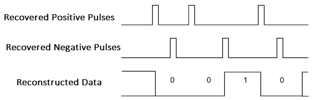
Data transmitted on the AS-i interface exists in non-zero-returning forms. It is encoded in Manchester format. The Manchester coded line currents are then differentiated for alternating pulse modulation (APM). AMP signals are AC coupled to the line and superimposed at the +/-2V DC level.

On the receiver side, the positive and negative pulses are recovered and reconstructed into the original data.
AS-i protocol
The AS-i mater searches each field device for a string. The master and slave have a maximum of 5ms or 10ms to exchange messages depending on the AS-i slave's addressing mode. When polling a slave, the master communicates a 14-bit call to the slave device. The 14-bit frame consists of 1 start bit (MSB), a control bit, 5-bit address, 5-bit command or data, a parity bit, and an end bit (LSB). Slave devices respond by transmitting a 7-bit frame, which consists of 1 start bit (MSB), 4-bit data requested by the master, a parity bit, and a stop bit (LSB).

AS-i safety at work
The AS-i can also connect workplace safety components such as emergency stop buttons, laser scanners, safety light barriers and door contacts. This feature is called “AS-i Occupational Safety”. The typical AS-i remains unchanged after the feature is added. The function is enabled by simply adding a safety monitor and safety slaves to the AS-i. The interface can then transfer standard and safety-oriented data from the safety slaves to the safety monitor. The configuration works even without fail-safe PLC or any specialized AS-i master.
Secure AS-i slaves continue to acquire data from secure inputs. Safety-oriented data is communicated to the safety monitor on the same bus via a dynamic and secure protocol. According to the protocol, the safety monitor seeks a specific response from the safety slaves in each cycle. The data frame sent as a response by the slave is dynamically changed according to an algorithm. A shutdown logic is configured accordingly in the safety monitor. If the security monitor does not receive the expected data frame from a respective security node, this will be interpreted as an alarm and a shutdown procedure will be initiated within a maximum response time of 40 ms.
ASI-safe is a system certified by TUV up to Safety Integrity Level 3 (SIL 3). This is an excellent way to add security to your automation environment at no additional cost.
Analog transmission on the AS-i bus
The AS-i bus is capable of transmitting digitized analog values. For analog transmission, the 4-bit output on a standard AS-i slave is divided into three analog bits and a handshake bit. The AS-i master starts analog mode in the first cycle. The reverse is also possible. The AS-i master can also send analog values to a slave. Processing technologies largely utilize analog transmission via AS-i.
AS-i applications
AS-i is a global standard. It has been widely adopted around the world to network binary actuators and sensors for factory automation, industrial process control, and building automation.