
 Modbus is a popular low-speed serial communication protocol widely used in the automation industry. The protocol was developed by Modicon (now acquired by Schneider Electric) in 1979 for their own programmable logic controllers. The protocol served as a link between PLCs and intelligent automation devices. Now an open protocol maintained by the Modbus Organization, Modbus has been very popular among automation engineers since its inception. The protocol is widely used for industrial monitoring and control, mainly with PLCs.
The serial protocol is based on master-slave configuration and is capable of configuring communication from a Modbus client with up to 247 Modbus servers. The physical interface is facilitated on the devices by standard RS-485 or RS-232 ports. The bus is shielded or unshielded twisted pair cable terminated at 150 ohms at both ends. The cable can be easily connected to devices using a 9-pin D-shell, screw terminals or RJ-45 connectors.
Modbus is a point-to-point or multidrop network using a series connection or taps. All communication in a Modbus network is controlled and managed by the master (i.e. the Modbus client). Modbus is widely used to connect instrumentation and control devices to a controller or data collection devices. Typically, the data collection device or Modbus client is a supervisory computer within a human-machine interface (HMI) or supervisory control and data acquisition (SCADA) system. Remote terminal units (RTU), including sensor modules, programmable logic controller (PLC) or programmable automation controller (PAC), are Modbus servers. Modbus is supported by almost all commercial HMI, SCADA, OPC and data acquisition software, allowing hassle-free integration of Modbus-compatible equipment with any Industrial Automation System (IAS) or Building Management System (BMS).
Why Modbus is so popular
Modbus is used by manufacturers in a variety of industries and has become quite popular due, in part, to its simplicity. It is an open standard; therefore, manufacturers can incorporate the RTU version of Modbus into their equipment without paying any royalties. The protocol can even be implemented on prototyping boards like Arduino. In fact, the communication protocol can be easily implemented on any microcontroller or computer. Data communication is performed via request-response and messages have a fixed frame format.
Initially developed as an application layer protocol for data transfer across the serial layer, there are currently three versions of the Modbus protocol: two for serial lines – Modbus RTU and Modbus ASCII; and one for Ethernet (TCP/IP and UDP) — Modbus TCP. Although relatively simplistic, the protocol still allows for message verification with an accuracy of over 99%. Modbus RTU has cyclic redundant checksums (CRC) and Modbus ASCII has longitudinal redundancy checks (LRC) for error checking.
Despite its beginnings in the 1970s, the protocol's implementation required minimal RAM and memory resources. In the 1970s, when computer technology as well as embedded technologies were not as advanced as they are today, a lightweight protocol like Modbus was especially attractive. Modbus' popularity has never waned.
Range and data rate
The default Modbus data rate is 9600 b/s or 19.2 kb/s. Typically, 19.2 kb/s is the standard rate. The data rate can be reduced to 4800 b/s, 2400 b/s, etc. The maximum data rate is 115.2 kb/s. At a standard data rate of 9,600 b/s, Modbus can have a maximum range of 1,000 meters. If the data rate increases, the range will be reduced. The length of the tap must always be less than 20 meters.
Logical levels
On a Modbus, a binary 0 is represented by a voltage level of +2 to +6V. Binary 1 is represented by a voltage level of -2 to -6V.
Layers
Initially, Modbus was a single protocol implemented at the serial layer. Application data units were introduced to allow implementation on serial networks, as well as on TCP/IP and UDP networks when the protocol was implemented for Ethernet. The protocol is now divided into two layers – the core layer and the network layer. The core layer defines the Protocol Data Unit (PDU), while the network layer defines the Application Data Unit (ADU). The PDU can be transmitted over the UDP network even without defining any application data units.
The serial versions of Modbus (i.e. Modbus RTU and Modbus ASCII) require only PDU, while the Ethernet version (i.e. Modbus TCP) requires PDU and ADU.
Network and communication
Modbus is a request-response protocol implemented in a master-slave configuration. There are two types of devices — Modbus Client and Modbus Server. The Modbus Client is the master and is usually a supervisor computer within a SCADA or HMI system. Modbus servers are slaves and are usually remote terminal units such as sensor modules, PLCs and PACs.
Serial versions of Modbus support communication from a single client with up to 247 Modbus servers. Since RS-485 and RS-232 ports are common for Modbus implementation, if RS-232 port is used, the maximum number of Modbus servers can be up to 247, but if RS-485 ports are used, the maximum number of Modbus servers are limited to 32 due to practical limitations of the RS-485 standard. There can be unlimited multiple clients and servers as the Ethernet version of Modbus has an additional 6 byte header for Internet routing
All data communication is controlled by the Modbus client via request-response. In Modbus, data is transferred in bytes. In the RTU version, each byte is encoded in an 11-bit asynchronous frame consisting of a start bit, a data byte, even parity, and a stop bit. In the ASCII version, each byte is encoded in a 10-bit frame consisting of a start bit, 7-bit data, 1 odd or even parity bit, or no bit if there is no parity, and 1 stop bit if parity is used, otherwise 2 stop for a while.
A message communicated between the master/client and the slave/server is called a Protocol Data Unit (PDU). The PDU consists of the slave address, function code (command), data, and checksum (CRC or LRC).
The master sends a request to one of the slaves identified by the slave's address. The slave address is one byte long and can have a value between 0 and 255. According to the protocol, slave address 0 is reserved for broadcast messages and slave addresses that identify slave devices cannot exceed 247. The function code is again one byte long and tells the addressed slave device what type of action to take. Function codes in the range 1 to 255 are valid, of which 128 to 255 are reserved for exception responses. Action is a read or write operation where the data in a request provides additional information needed to perform the action. For example, you can specify where to start reading and how much data should be read. CRC is applied for error checking in the RTU version, while LRC is applied for error checking in the ASCII version.
When the master makes a request to an addressed slave, it returns a response. The slave address and function code are repeated in the same response. The data contains the values requested by the master. If an error occurs while performing the requested action, the function code is modified and the data contains code that describes the error. Again, CRC or LRC, depending on RTU or ASCII framing respectively, are used to ensure the integrity of the message or PDU.
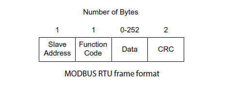
In RTU framing, each byte represents two 4-bit hexadecimal characters in an 11-bit frame. The PDU consists of a 1-byte slave address, 1-byte function code, 0 to 252 byte data, and 2-byte CRC.
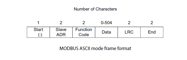
In ASCII framing, each byte represents two ASCII characters in a 10-bit frame. The PDU consists of a 1 character long starting character, a 2 character long slave address, a 2 character long function code, 0 to 504 character long data, a 2 character long LRC, and a 2 character long ending character. characters. The starting character is always a colon (:) or ASCII 3A hexadecimal. The final character is always a carriage return with line feed (ASCII 0D and 0A hexadecimal). Each PDU in the RTU as well as the ASCII version is separated by 28 bits or 3.5 characters.
Both RTU and ASCII versions of Modbus are almost similar except some differences. In the RTU framework, bytes are presented in binary format, while in the ASCII framework, bytes are presented as readable 4-bit ASCII characters. The ASCII frame has text start and end characters, while in the RTU frame the 28-bit separation between PDUs/messages is interpreted to detect the start and end of the frame. Because the RTU framework uses shorter messages, it is faster than the ASCII version. The ASCII version has the advantage that intervals of up to one second can elapse between message characters. If the interval exceeds one second, the equipment considers it a transmission error.
The PDU in the TCP version of Modbus consists of a 2-byte transaction ID, a 2-byte protocol field, a 2-byte length field, a 1-byte slave address, and a 1 to 252 byte slave address. message field.
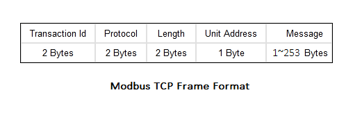
The transaction ID identifies the transaction and the protocol is always set to 0 to indicate Modbus. The length indicates the number of following bytes. This is followed by a 1-byte slave address. The message field is an RTU version similar to the Modbus frame consisting of the function code and data. The maximum message field size can be 253 bytes (i.e. 1 byte for function code and maximum 252 bytes for data as in the RTU frame).
The least significant bit is sent first in all versions – RTU, ASCII and TCP. Modbus-compatible equipment cannot automatically detect the baud rate, so the same baud rate needs to be explicitly set at both the client and server ends of the bus. The Modbus PDU supports a format that can only send data, with no ability to send parameters between communication devices.
Data types
There are two types of data in Modbus – Coils and Registers. Coils are single bits that can be 0 (OFF) or 1 (ON). The coils can be discrete output coils or discrete input contacts. Discrete input contacts are the status of a physical discrete input as ON or OFF. Discrete output coils have the physical discrete output signal status as ON or OFF.
Registers are 16-bit unsigned registers that can hold a value that represents a floating-point number, ASCII text, a queue, or a table. A register by itself only stores positive values in the range 0 to 65535, i.e. 0x0000 to 0xFFFF hexadecimal. 16-bit data stored in registers can be interpreted as a 16-bit unsigned integer, a 16-bit signed integer, a 2-character ASCII string, or a discrete ON/OFF value by the Modbus client. 32-bit data stored in registers can be interpreted as a 32-bit unsigned integer, a 32-bit signed integer, a 4-character ASCII string, or a 32-bit double precision floating point number by the Modbus client.
There are two types of registers – analog input registers and analog output hold registers. Like discrete input contacts (coils), input registers store the status of an external input as a value between 0 and 65535 (0x0000 and 0xFFFF). In the past, input registers were generally used to store digital representations of the value of analog inputs that could be voltage or current signals. Output hold registers are used to store data in the device. Now, since most Modbus compatible equipment are not input/output devices, input registers are also used to store data.
How the server stores data
In a Modbus server, such as a sensor module, PLC or PAC, data is organized into four tables or databases. There are two databases for storing discrete on/off values or coils. These databases store discrete output coils and discrete input contacts separately. So, there are two databases for storing numeric values or registers that store analog input registers and analog output holding registers separately.
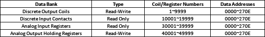
Each database can store 9,999 values. For example, the databases for discrete output coils and discrete input contacts can store 9,999 bits each, in the range 0000 to 270E. The databases for analog input registers and analog output hold registers can store 9,999 words each, in the range 0000 to 270E, where each word is 16 bits long.
The databases for discrete output coils and analog output hold registers are read-write type, while the databases for discrete input contacts and analog input registers are read-only type.
Values in databases are accessed by locale names. The database for discrete output coils, discrete input contacts, analog input registers, and analog output hold registers have locations in the range 1~9999, 10001~19999, 30001~39999, and 40001~49999, respectively. The structure and nature of four databases on a Modbus server are summarized in the following table.
Conclusion
Modbus is a widely used industrial communications protocol often used with PLCs. The protocol has three versions – RTU, ASCII and Modbus. The RTU version, being open standard and faster, is more commonly used by manufacturers. With shorter messages, RTU-framed Modbus messages can be updated within a 100 millisecond interval. Modbus is supported by almost all commercial HMI, SCADA, OPC and data acquisition software, making it easy to integrate Modbus-compatible equipment into any industrial automation system or building management system.
(tagsToTranslate)Arduino