
In electrical engineering, the search for efficient use of energy is inexhaustible. A central aspect of this search is power factor correction, a technique that optimizes energy consumption and improves the overall efficiency of electrical systems. Central to these efforts is the sophisticated use of synchronous motors. These remarkable machines, which enable dynamic power factor adjustment, play a critical role in defining the power factor landscape. This research investigates the fascinating area of using synchronous motors for power factor correction. By understanding their function and the mechanisms they employ, we discover a crucial chapter on the path to more resourceful and sustainable energy management.
Synchronous motors and power factor improvement
The power factor of a synchronous motor changes with excitation, going from lagging to 1 to leading. This feature improves the power factor of loads with low lagging power factor. Mechanically unloaded synchronous motors with advanced power factor are synchronous capacitors.
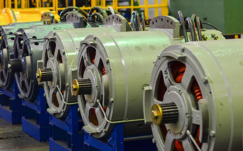
Factories often use induction motors with a power factor of 0.8, which drops to 0.6 under light load. To improve the power factor, synchronous capacitors can be connected in parallel.
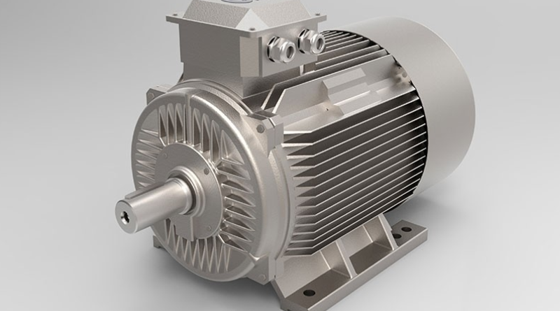
Components such as capacitors, inductors and resistors are crucial in electrical circuits. Synchronous motors rely on features such as armature, controller, main motor, air gap and much more for their functionality. Understanding these concepts is essential to understand their importance in improving power factor.
Idle test and locked rotor test
Idle test and locked rotor test are two basic tests used in the field of electrical engineering to evaluate the performance and functionality of electric motors. As the name suggests, the idle test involves running the engine without any external load. This test helps determine important parameters such as no-load current, no-load speed and rotational losses and provides information about the efficiency and magnetic properties of the motor. The locked rotor test, on the other hand, intentionally blocks rotor movement while the motor is supplied with rated voltage. This test helps measure parameters such as locked-rotor current, torque, and impedance, which are critical in evaluating the starting ability and overall health of the motor.Synchronous Phase Modifier
A synchronous motor controls the voltage of a transmission line at the receiving end. Synchronous motors in this application run without load and draw maximum current. For this purpose, the synchronous motor is called a synchronous phase converter. Because the action of the synchronous capacitor improves the power factor of the system, the voltage drop between the transmitting and receiving ends of the line is reduced and line regulation is improved.
Power factor correction with synchronous capacitor
Synchronous motor for power factor correction
In the figure above, V is the reference pointer I C is the load current with lagging power factor cosθ 1 . OA is the active component of the charging current and AC is the reactive component. If the synchronous motor is operated as a synchronous capacitor and losses are neglected, OD represents the current consumed; it's 90 ahead. If this value is equal to the AC reactive load current component, the resultant of the powers consumed by the load and the synchronous motor is just OA, giving the load the same output power in KW, but improving the load's power factor to 1 since OA is in phase with V is.
L C = L M sinθ 1 is the prerequisite for improving the load power factor to unity under certain operating conditions.
The required KVA power of the synchronous capacitor is I C x V volt-amperes per phase or √3VI C /1000 KVA would be the three-phase power.
The rated power of the synchronous capacitor is √3VI C /1000 KVA. If the power factor is improved to less than 1, the required capacity of the synchronous capacitor will be smaller.
OD – reactive (main) component of the synchronous capacitor
If this value is equal to BC, then the resulting load current vector is OB and the new load power factor is cosθ 2 . Then
EU C = I M sinθ 1 – I M sinθ 2
The active component of the charge is reduced from AC to AB. The rated power of the synchronous capacitor required for this purpose is
= √3VI C /1000KVA
Conclusion
With their diverse applications, synchronous motors play an important role in electrical systems. They provide an effective power factor correction solution by acting like synchronous capacitors, drawing reactive current and improving the overall power factor. Synchronous motors are particularly useful in induction motor scenarios with low lagging power factors and can optimize energy usage.
No-load and stall rotor tests are commonly used to evaluate the performance of synchronous motors. They provide important information about their efficiency and properties. The implementation of synchronous motors as phase converters ensures efficient power factor correction and contributes to a more stable and regulated electrical system.
The main components of synchronous motors such as poles, stators, rotors and rotating magnetic fields are crucial for their operation and synchronization with the grid frequency. Furthermore, excitation voltage and field current affect the behavior of the motor, while differences in slip and speed affect its performance.
In summary, synchronous motors provide a practical solution for power factor correction in various electrical systems and are therefore crucial for achieving energy efficiency and stable energy use.
Common questions
1. What is the power factor correction of a synchronous motor?
Power factor correction of a synchronous motor is a method of improving power factor by using capacitors to compensate reactive power (kVAR) and increase efficiency.
2. How do capacitors solve power factor problems?
Capacitors compensate for delayed reactive currents caused by inductive loads, improving power factor, reducing losses and increasing efficiency.
3. What are the advantages of power factor correction for synchronous motors?
Power factor correction reduces electricity costs, improves voltage regulation, extends device life, and improves power quality.
4. How is power factor correction of a synchronous motor implemented?
To implement power factor correction, capacitor banks must be added in parallel with inductive loads and sized appropriately for effective discipline.
5. Can power factor correction solve all power-related problems?
Power factor correction improves power factor and reactive power, but additional measures may be needed for other factors such as harmonics and power quality.


1comment
Bom material didatico