This tutorial is about how to control stepper motor over WiFi via desktop or mobile browser using nodemcu esp8266 WiFi module. Nodemcu will work as a server and serve a web page. The web page contains the stepper motor control buttons. The stepper motor takes steps to complete a full 360 degree rotation. The number of steps required to complete a full rotation depends on the specific step angle of the motor. Typically step angles are 0.9 degrees and 1.8 degrees per step. Stepper motors are capable of delivering high torque at small angles. They consume high power to produce high torque. Their small steps have made them popular for use in projects where high precision is required. They are popularly used in the automobile industry. Stepper motors power robotic arms used in automobile manufacturing. Stepper motor drive arms at such a precise angle that one arm can easily insert a small nut into car parts whenever needed. Stepper motors are also the main part of 3D printers. Even normal printers and disk drivers use stepper motors to rotate disks precisely.
NEMA 17 stepper motor
Stepper motors are brushless DC motors. Stepper motors are divided into two general categories: unipolar stepper motors and bipolar stepper motors. You can find many tutorials on the internet that explain the difference between the two. For this project I will use bipolar stepper motor. The bipolar stepper motor that I will use in the project is NEMA 17. Nema 17 is a popular 4-wire, 2-coil stepper motor. Its pitch angle is 1.8 degrees. Therefore, for a complete rotation, 200 steps are needed (200 x 1.8 = 360). Normal power consumption for NEMA 17 is 5 to 12 volts, and it draws 1 to 1.5 amps of direct current when a load is connected to it.
Four NEMA 17 wires have different colors. Typically the wires are red, blue, green and black. Red and blue represent the first coil and green and black represent the second coil. In some engines, blue is replaced by yellow, and black by gray. If you are going to use NEMA 17 in a DIY project, first make sure you are using the correct pair of coils with the colors.
A4988 Stepper Motor Driver
Stepper motors consume a lot of energy when moving loads. When there is no load, current consumption is drastically reduced. To supply the amount of power discussed above to the stepper motor (NEMA 17 12 volts 1.5 amps), we need an external power supply. With an external power supply we also need a circuit that can control the motor rotation perfectly and easily. Traditionally, a combination of transistors or mosfets known as H-Bridge circuit is used to control the stepper motor with microcontrollers. Making an H-Bridge circuit and testing it is a time-consuming task. Nowadays, a variety of pre-assembled H-Bridge boards or motor controller drivers are available on the market. They are not only cheap but also easy to work with. For this project I decided to use one of the pre-assembled H-Bridge stepper motor driver boards. The stepper motor driver I selected for the project is the A4988. A4988 is a bipolar stepper motor driver. The A4988's power requirements are 3.3 volts to 5 volts. It can easily drive a two-coil stepper motor. External power is supplied to it and its internal H-Bridge circuit splits the power between the coils when the coils are energized.
I explained each pin of the A4988 bipolar stepper motor driver in another tutorial. Pin configuration and steepest engine rotation mode are also explained in the tutorial. I suggest you go through this tutorial first to familiarize yourself with the A4988 driver and its operational requirements. If you follow that short tutorial and its part on A4988 motor driver, you can easily understand the code and circuit diagram below.
A4988 stepper motor driver pin configuration and connection requirements
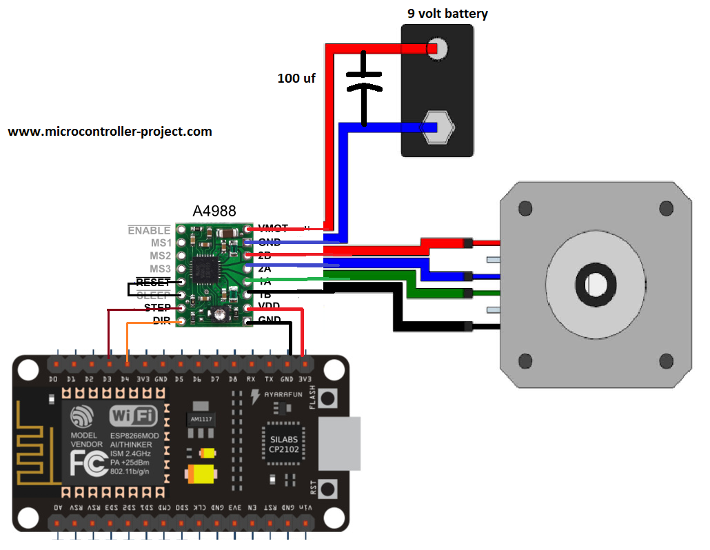
Project circuit diagram
The 9 volt battery is connected between the Vmot and gnd pins of the A4988 motor driver. 9 volts are enough to power the NEMA 17 coils. The stepper motor coils are connected to pins 1A, 1B, 2A, and 2B of the A4988 stepper motor driver. The A4988 driver is powered by 3.3 volt nodemcu output power rail. The stepper pin of the A4988 is connected to the D3 or GPIO-0 pin of the nodemcu esp866 12e. The Dir pin of the A4988 is connected to D4 of the nodemcu WiFi module. The Reset and Sleep pins are interconnected. A4988 mode pins Ms1, Ms2 and Ms3 are left open. In this configuration the motor is placed in full step mode. The activation pin is also open. It is internally pulled down and the module always remains in enabled mode. Once again, I encourage you to follow the tutorial recommended above, otherwise you will not be able to understand the circuit discussed earlier and the code that will be discussed later.
Nodemcu esp8266 12 and controlling stepper motor via WiFi
Coming to the project code. First, the ESP8266WiFi library is included in the code. This library initializes the server and WiFi of the nodemcu esp8266 WiFi module. The SSID and PASSWORD of the WiFi you want to connect your nodemcu WiFi module to is required. It will be your home router's WiFi password and the SSID if you are testing the DIY project at home. Enter the password and SSID in the code before proceeding. Enter the ssid and password in double quotes.
const char* ssid = “Your SSID”;
const char* password = “Your Wifi password”;
Next, the A4988 control pins are defined. The stepper pin of the A4988 stepper motor driver is connected to the GPIO-0 or D3 pin of the nodemcu WiFi module. The direction pin of A4988 is connected to GPIO-2 of D4 pin of esp8266 nodemcu board.
In the configuration function, the control pins are declared as output. The Arduino ide serial monitor starts up with baud rate of 115200. The server starts and the IP of the web page is published. I'll talk more about this after the code. In the loop function, the main logic of the program is running. In the loop function, the server is waiting for a request from the client. Once the server receives the request from the client, it handles it and responds to the request.
|
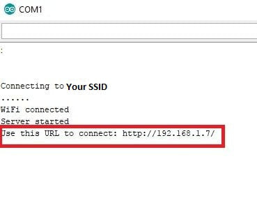
Just make the circuit and download the above code into it. Before sending code to nodemcu, first make sure the correct board is selected. After downloading the code into nodemcu, open the arduino serial monitor in the arduino ide. As soon as you open the serial monitor, you will see nodemcu asking your router for an IP assignment. After IP assignment, nodemcu will start its server. After the server boots, the server address will be printed on the serial monitor window. This address is actually the address of the web page that contains the stepper motor controls. You must enter this address in your browser to access the web page.
|
|
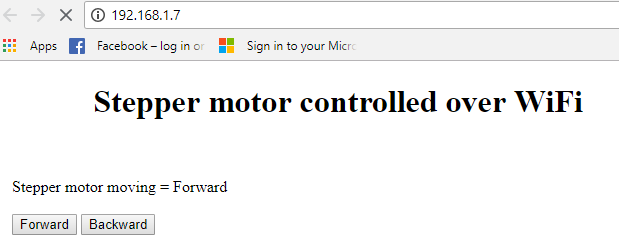
The example HTTP web page address is provided in the upper right corner. One more important thing. Server (nodemcu, esp8266) and client (mobile, desktop, laptop or notebook) must be connected to the same WiFi network. If any client module or server is connected to another network, the web page will not appear in your browser. After entering the IP into the browser, the following web page will appear in the browser.
Stepper motor WiFi control with nodemcu esp8266
|
The web page has two buttons, one for forward and one for back. If you press the forward button, the motor will move 50 steps per head. If you press back, the motor will change direction and start moving 50 steps back. Remember we are using NEMA 17 stepper motor and it takes 200 steps to complete one rotation. So if I move the motor 50 steps on each button press. This means I'm moving the stepper motor axis 90 degrees with each button press. A for loop is executed 50 times to allow the stepper motor to take 50 steps. So now in our case the stepper motor is taking 4 steps to complete 360 degree rotation or 1 step to move 90 degrees.
|

Stepper Motor Step Angle Count
|
Future Recommendations
This tutorial is a simple tutorial on how to control stepper motor over WiFi using nodemcu WiFi module. In the future, you can test other stepper motor rotation modes in 1/4, 1/8, and 1/16 micro steps. You can also enter steps manually on the web page and move the motor according to the entered number. A bar can be inserted into the web page and the position of the engine can be controlled through it using the AJAX web development language.
Download the project code. The folder contains the .ino file of the nodemcu arduino code. The code is open source and can be used and changed. Please provide us with your feedback on the tutorial.
Code/Files