Nowadays, children often fall into the uncovered well and become trapped. It is very difficult and risky to rescue trapped children. A short delay in rescue could cost the child's life. The project objective is to build and design a well rescue robot . The project objective is to build and design a well rescue robot. This project is a human-controlled robot that offers a detailed look at safely rescuing and the steps taken to achieve it. The project aims to design a “Robot to rescue a child from a well” that works according to user commands given on the PC. The project also utilized picking and placing objects based on the arm design.
The robot is operated through PC using wireless technology using zigbee and using wireless camera we can view audio and video on TV. This robot has a high-power LED that acts as a light source when the light intensity inside the tube is low. It is a low-cost robot used to monitor changes in different parameters in industrial pipes. By connecting the temperature sensor to the robot we can obtain the temperature of the dangerous zones on the PC itself. By connecting the smoke sensor to the robot we can obtain information related to the concentration of smoke or gases in the respective fields. Wireless control of the robot via PC using zigbee technology. Live and video can be seen on TV. Implementation of the pick and place concept in the robot. DC motor based gripper operation for robotic arm. The robot also has beacon vision with LEDs and turns on when the LDR sensor detects darkness inside the well. By connecting the temperature sensor to the robot we can obtain the temperature of the dangerous zones on the PC itself. By connecting the smoke sensor to the robot we can obtain information related to the concentration of smoke or gases in the respective fields. We can develop a robotic machine that can remove the trapped body systematically. He will also perform various life-saving operations for patients, such as providing oxygen. A video camera for closely observing the actual situation and continuous interaction with the patient can also be attached. In this alternative scenario, there is no need to dig any hole parallel to the well. The remote controlled robot will descend the well and perform the action
The project aims to design a robot to rescue a child from a well that works according to user commands given on the PC. The project also utilized picking and placing objects based on the arm design. The robot is operated through PC using wireless zigbee technology and using wireless camera we can view audio and video on TV. This robot has a high-power LED that acts as a light source when the light intensity is inside the tube. By connecting the temperature sensor to the robot we can obtain the temperature of the dangerous zones on the PC itself. By connecting the smoke sensor to the robot we can obtain information related to the concentration of smoke or gases in the respective fields.
Keil implementation
KEIL IMPLEMENTATION METHODS
1. Click on the Keil Vision icon on the desktop
2. The following fig will appear
Figure 1: Screenshot of Keil IDE
3. Click the Project menu in the title bar
4. Then click on New Project

Figure 2: Screenshot of opening a new project in Keil IDE
5. Save the project by typing the appropriate project name without extension in its own folder located in C: or D:

Figure 3: Screenshot saving a project in Keil IDE
6. Then click the Save button above.
7. Select the component for your project. i.e. Atmel……
8. Click the + symbol next to Atmel

Figure 4: Screenshot of microcontroller family selection in Keil IDE
9. Select AT89S52 as in the example shown below

Figure 5: Screenshot of 8051 microcontroller selection in Keil IDE
10. Then click “OK”
11. The following figure will appear

Figure 6: Screenshot of the message requesting to copy the default Keil IDE initialization code when creating a new project for the 8051 microcontroller
12. Then click YES or NO………mainly “NO” for 8052 programming.
13. Now your project is ready to USE
14. Now double click on Target1, you will get another option “Source group 1” as shown on the next page.

Figure 7: Screenshot of the project workspace in Keil IDE
15. Click on the file option in the menu bar and select “new”

Figure 8: Screenshot of creating a new file in Keil IDE
16. The next screen will be as shown on the next page, just maximize it by double clicking on its blue border.

Figure 9: Screenshot of the Code Editor window in Keil IDE
17. Now start writing the program in “C” or “ASM”
18. For a program written in Assembly, save it with the “. asm” and for “C” based programs save it with “.C” extension

Figure 10: Screenshot saving assembly code in Keil IDE
19. Now right-click on the Source 1 group and click on “ Add files to group source ”

Figure 11: Screenshot of adding a file to the source group in Keil IDE
20. Now you will have another window, in which the “C” files will appear by default.

Figure 12: Screenshot saving embedded C code in Keil IDE
21. Now select as per the file extension given while saving the file
22. Just click once on the “ ADD ” option
23. Now press the F7 function key to compile. Any error will appear if this happens.

Figure 13: Screenshot of project code compilation in Keil IDE
24. If the file contains no errors, press Control+F5 simultaneously.
25. The new window is as follows

Figure 14: Screenshot of successful code compilation in Keil IDE
26. Then click “OK”
27. Now click on Peripherals in the menu bar and check the required port as shown in the figure below

Figure 15: Screenshot of I/O port selection in Keil IDE
28. Drag the port to the side and click on the program file.

Figure 16: Screenshot of I/O port simulation in Keil IDE
29. Now keep pressing “F11” function key slowly and observe the operation.
30. You are running your program successfully
PROG ISP
1. Place the IC on the development board and connect it to the computer's serial port.
2. Click PROG ISP and open the software

Figure 17: Screenshot of the PROG ISP application
3. Now click on the LOAD FLASH button and look for the HEX file that needs to be dumped.

Figure 18: Screenshot of loading the hexadecimal file into PROG ISP
4. Now the source code is dumped into the IC.
AT89S52 Microcontroller
A microcontroller is a general-purpose device intended to read data, perform limited calculations on that data, and control its environment based on those calculations. The main use of a microcontroller is to control the operation of a machine using a fixed program stored in ROM and which does not change during the life of the system.
Characteristics
· Compatible with MCS-51 products
8K bytes of system programmable flash memory (ISP)
Operating range 4.0V to 5.5V
· Three-level program memory lock
· 256 x 8-bit internal RAM
· 32 programmable I/O lines
· Three 16-bit timers/counters
· Eight interrupt sources
Full Duplex UART serial channel
Low power consumption idle and off modes
· Stop recovery from power off mode
· Surveillance timer
Additionally, the AT89S52 is designed with static logic for operation down to zero frequency and supports two software-selectable power saving modes. Idle mode stops the CPU while allowing the RAM, timers/counters, serial port, and interrupt system to continue functioning. Power-down mode saves the contents of RAM but freezes the oscillator, disabling all other chip functions until the next hardware interrupt or reset.
AT89S52 Microcontroller Pin Configuration

Figure 19: AT89S52 8051 microcontroller pin diagram
Pin Description
CCV
supply voltage
GND
Floor
Port 0
Port 0 is an 8-bit open-drain bidirectional I/O port. As an output port, each pin can absorb eight TTL inputs. When 1s are written to port 0 pins, the pins can be used as high impedance inputs. Port 0 can also be configured to be the multiplexed low-order address/data bus during access to external program and data memory. In this mode, P0 has internal pull-ups. External pull-ups are required during program verification.
Port 1
Port 1 is an 8-bit bidirectional I/O port with internal pull-ups. Port 1 output buffers can collect/source TTL inputs. When 1s are written to the port 1 pins, they are pulled up by the internal pull-ups and can be used as inputs.
Port 2
Port 2 is an 8-bit bidirectional I/O port with internal pull-ups. Port 2 output buffers can capture/source TTL inputs. When 1s are written to the port 2 pins, they are pulled up by the internal pull-ups and can be used as inputs. As inputs, the P2 pins that are being externally pulled down will supply current because of the internal pull-ups.
Port 3
Port 3 is an 8-bit bidirectional I/O port with internal pull-ups. The port 3 output buffers can collect/source four inputs. When 1s are written to the port 3 pins, they are pulled up by the internal pull-ups and can be used as inputs. As inputs, Port 3 pins that are being pulled down externally will supply current because of the internal pull-ups.
| DOOR PIN | ALTERNATIVE FUNCTION |
| P3.0 | RXD (serial input port) |
| P 3.1 | TXD (serial input port) |
| P3.2 | INT0(external interrupt 0) |
| P 3.3 | INT1 (external interrupt 1) |
| P 3.4 | T0 (external timer input 0) |
| P 3.5 | T1 (external timer input 1) |
| P 3.6 | WR (write strobe to external data memory) |
| P3.7 | RD (External Data Memory Read Strobe) |
PORT 3 DESCRIPTION
RST
Resetting input A on this pin for two machine cycles while the oscillator is running resets the device.
ALE/PROG
Address Latch Enable is an output pulse to latch the lower byte of the address during external memory access. This pin is also the program pulse (PROG) input during Flash programming.
In normal operation, the ALE is output at a constant rate of 1/16 of the oscillator frequency and can be used for external timing or clocking purposes. Note, however, that an ALE pulse is ignored during each access to external data memory.
PSEN
Program Store Enable is the read strobe for external program memory when the AT89S52 is executing code from external program memory. PSEN is activated twice each machine cycle, except that two PSEN activations are ignored during each access to external data memory.
EA/VPP
External Access Enable (EA) must be bound to GND to allow the device to fetch code from external program memory locations. Note, however, that if lock bit 1 is programmed, the EA will be internally locked on reset. The EA must be linked to Vcc for internal program executions. This pin also receives the 12 volt programming enable voltage (Vpp) during Flash programming.
XTAL1 and XTAL2
XTAL1 forms the input to the inverting oscillator amplifier and the input to the internal clock operating circuit. The output of the inverting oscillator amplifier is obtained from the XTAL2.
AT89S52 block diagram

Figure 20: AT89S52 8051 microcontroller block diagram
ARCHITECTURE
Operational description
The detailed description of the AT89S52 included in this description is:
• Memory map and records
• Timer/Counters
• Interruption system
Memory map and records
Memory
MCS-51 devices have a separate address space for program and data memory. Up to 64K bytes of external program and data memory can be addressed.
Program memory
If the EA pin is connected to GND, all program fetches will be directed to external memory. On the AT89S52, if the EA is connected to the VCC, program searches for addresses 0000H through 1FFFH are directed to internal memory and program searches for addresses 2000H through FFFFH are to external memory.
Data memory
The AT89S52 implements 256 bytes of RAM on the chip. The upper 128 bytes occupy address space parallel to the special function registers. This means that the top 128 bytes have the same addresses as the SFR space, but are physically separated from the SFR space.
Timer/counters
The AT89S52 has three 16-bit timer/counter registers. All can be configured to operate as timers or event counters. Like Timer, the register is incremented with each machine cycle. Thus, the recorder counts the machine cycles. Since a machine cycle consists of 12 oscillator periods, the count rate is 1/12 of the oscillator frequency.
As a counter, the register is incremented in response to a transition from 1 to 0 on its corresponding external input pin, T0 and T1. The external input is sampled every machine cycle. When samples show a maximum in one cycle and a minimum in the next cycle, the count is incremented. Since it takes two machine cycles (24 oscillator periods) to recognize a transition from 1 to 0, the maximum counting rate is 1/24 of the oscillator frequency. There are no restrictions on the duty cycle of the external input signal, but it must be maintained for at least one full machine cycle to ensure that a given level is sampled at least once before changing.
Interruptions
The AT89S52 has a total of six interrupt vectors: two external interrupts (INT0 and INT1), three timer interrupts (Timers0, 1, and 2), and the serial port interrupt. They are shown in the table below. Each of these interrupt sources can be enabled or disabled individually by setting or clearing a bit in the IE Special Function Register. IE also contains a global disable bit, EA, which disables all interrupts at once.
IE.7
| Symbol | Position | Function |
| AND THE | Disables all interrupts. If EA = 0,
no interruptions are recognized. If EA = 1, each interrupt source is enabled or disabled individually setting or deselecting its activation chunk |
|
| – | IE.6 | Reserved. |
| ET2 | IE.5 | Timer interrupt enable bit 2. |
| ES | IE.4 | Serial port interrupt enable bit. |
| ET1 | IE.3 | Timer 1 interrupt enable bit. |
| EX1 | IE.2 | External interrupt enable bit 1. |
| ET0 | IE.1 | Timer interrupt enable bit 0. |
| EX0 | IE.0 | External interrupt enable bit 0. |
INTERRUPTIONS
BLOCK DIAGRAM
Master control system: This system works as a transceiver. When we give commands to the robot, it acts as a transmitter. When we receive temperature and smoke values from the sensors, it acts as a receiver.

Figure 21: Block diagram of Zigbee based transmitter for 8051 microcontroller based rescue robot
RECEIVER

Figure 22: Block diagram of Zigbee-based receiver for 8051 microcontroller-based Rescue Robot
FIGURE BLOCK DIAGRAM
The description of the block diagram is as follows:
The control device of the entire system is a microcontroller. Whenever the user presses a button on the PC keyboard, the data related to that specific button is sent through the zigbee module interfaced with the PC. The robot also has an arm to lift the obstacle using a servo motor. The system also has beacon vision with high-power LEDs and turns on when the LDR sensor detects darkness inside the well.
This data will be received by the zigbee module in the robot system and send it to the microcontroller which evaluates the relevant task according to the received information and acts according to the movement of the robot and arm. Live images from the robotic system's camera can be sent to the TV through the AV transmitter system. The microcontrollers used in the project are programmed in embedded C language.
Here we use 4 DC motors, two for robot steering and two for robot arm. LM293D is used to drive the motors. These motors are connected to port 0 of the microcontroller. LCD is used to display messages which are connected to port 2 of the microcontroller. Zigbee is interfaced with microcontroller using MAX 232. This project contains three sensors called temperature sensor, smoke sensor and LDR sensor. These three sensors are connected to port3 of the microcontroller.
Flowchart:

Figure 23: Flowchart for Rescue Robot C code based on 8051 microcontroller
The AT89S52 is a low-power, high-performance 8-bit CMOS microcontroller with 8K bytes of system-programmable Flash memory. The device is manufactured using Atmel's high-density non-volatile memory technology and is compatible with the industry standard 80C51 instruction set and pinout. On-chip Flash allows program memory to be reprogrammed into the system or by a conventional non-volatile memory program.
In this project we use these hardware Zigbee module, temperature, ldr, smoke sensor circuits, L293D motor driver ic, buzzer, MAX232 ic etc…,
+5 V regulated power supply is supplied to the sensor, L293D, MAX232, buzzer, AT89S52 MC circuits.
In this project there are two sections:
1)monitor section
2) robot section.
The monitor section controls the movement of the robot using the PC. By using the Hyper terminal on the PC we can send commands to control the robot's movement.
Command for robot operation:
The commands for the robot are F-> forward, B-> backward, L-> left, R-> right direction.
When you turn on the source we can see these commands being displayed on the PC. with this, we can give commands to the robot to move in different directions.
For example: if we want the robot to move forward, just type the capital letter 'F' in the hyperterminal. From the PC serial port, it is directly connected to the zigbee module as shown in the circuit diagram. PC sends signal to robot through zigbee module.
When the robot receives the signal from the monitor section using the zigbee module. The microcontroller will receive the commands from the zigbee module through the MAX 232. Then the microcontroller sends 0101 to the motor driver circuits on port pins P1^1, P1^2, P1^3, P1^4. Then, two motors will start rotating in forward directions so that the robot moves in forward directions. The same operation continues when we give the commands B, L, R for the backward, left and right directions.
On the LCD screen we can find displays for the robot’s movement directions…
Pick and Place The commands for the robot are O->claw open, C->claw closed, U->claw moves in the up direction, D->claw moves in the down direction. we can give these PC commands to the robot to choose and perform different actions.
For example: if we want the robot to choose an object, just type the capital letter 'C' in the hyperterminal. From the PC serial port, it is directly connected to the zigbee module as shown in the circuit diagram. PC sends signal to robot through zigbee module.
When the robot receives the signal from the monitor section using the zigbee module. The microcontroller will receive the commands from the zigbee module through the MAX 232. Then the microcontroller sends 1000 to the motor driver circuits on port pins P0^1, P0^2, P0^3, P0^4. Then, the motor will begin to rotate clockwise so that the clamp closes. The same operation continues when we give the commands C,U,D for the CLOSE, DOWN, UP directions.
The monitor sections receive information about the robot's operations and also send commands to the robot to move in different directions. The buzzer sounds for an indication. Each message will be displayed on the LCD screen.
When the temperature sensor (thermistor) connected to pin P3.2 and its sensors the temperature and output are provided to the microcontroller and the microcontroller sends commands to the monitor section which shows the message “temperature high” and also displayed on the LCD.
When the smoke sensor (mq-5) is connected to pin P3.3 and detects smoke and the output of the smoke sensor is given to the microcontroller and the microcontroller sends commands to monitor the section that displays the “high smoke” message and also displayed on the LCD.
When light is detected by the LDR it is connected to pin P3.4 and the microcontroller sends commands to the monitor section which is the message “light is low” and also displayed on the LCD.
LDR
WORKING:
A photoresistor or light-dependent resistor or CdS cell is a resistor whose resistance decreases with increasing intensity of incident light. It can also be called a photoconductor. A photoresistor is made from a high-resistance semiconductor. If the light falling on the device has a high enough frequency, the photons absorbed by the semiconductor will provide the bound electrons with enough energy to jump into the conduction band. The resulting free electron (and its hole partner) conducts electricity, thus decreasing resistance.
A photoelectric device can be intrinsic or extrinsic. An intrinsic semiconductor has its own charge carriers and is not an efficient semiconductor, for example silicon. In intrinsic devices, the only available electrons are in the valence band, and therefore the photon must have sufficient energy to excite the electron across the entire band gap. Extrinsic devices have impurities also called dopants, whose ground state energy is closer to the conduction band, since the electrons do not have as much to bounce around, lower energy photons (i.e. longer wavelengths and lower frequencies) lows) are sufficient to activate the device. If a silicon sample has some of its atoms replaced by phosphorus atoms (impurities), there will be extra electrons available for conduction. This is an example of an extrinsic semiconductor.
")
Figure 24: Representational Image of the Light Dependent Resistor (LDR)
A light-dependent resistor (LDR, photoconductor or photocell) is a device that has a resistance that varies according to the amount of light that falls on its surface. They will have a resistance of 1 MOhm in total darkness and a resistance of 1 to 10 kOhm in bright light. A photoelectric device can be intrinsic or extrinsic.
2 APPLICATIONS:
An LDR can even be used in a simple remote control circuit using the backlight of a cell phone to turn on a device – call the cell phone from anywhere in the world, it turns on the LDR and the lighting can be turned on remotely!
")
Figure 25: Image of Light Dependent Resistors (LDR)
There are two basic circuits that use light-dependent resistors – the first is activated by darkness, the second is activated by light.

Figure 26: Dark-activated light sensor circuit diagram
In the circuit diagram on the left, the LED lights up whenever the LDR is dark. The 10K variable resistor is used to adjust the level of darkness required before the LED turns on. The standard 10K resistor can be changed as needed to achieve the desired effect, although any replacement must be at least 1K to protect the transistor from being damaged by excessive current.
By swapping the LDR with the 10K and 10K variable resistors, the circuit will be activated by light. Whenever enough light falls on the LDR (manually adjusted using the 10K variable resistor), the LED will light up.

Figure 27: Light Activated Light Sensor Circuit Diagram
The circuits shown above are not useful in practice. In a real-world circuit, the LED (and resistor) between the positive voltage input (Vin) and the collector (C) of the transistor would be replaced by the device to be powered.
Thermistor
Thermistor is a type of resistor with resistance inversely proportional to its temperature. The word is a portmanteau of thermal and resistor . Samuel Ruben invented the thermistor in 1930 and received US patent #2,021,491.
Thermistors are widely used as starting current limiters, temperature sensors, self-resetting overload protectors, and self-regulating heating elements.
Assuming, as a first order approximation, that the relationship between resistance and temperature is linear, then:

Figure 28: Screenshot of resistance calculation for Thermister from the datasheet
Thermistors can be classified into two types depending on the sign of k . If k is positive, the resistance increases with increasing temperature, and the device is called a positive temperature coefficient ( PTC ) thermistor. If k is negative, the resistance decreases with increasing temperature, and the device is called a negative temperature coefficient ( NTC ) thermistor. Resistors that are not thermistors are designed to have k as close to zero as possible so that their resistance remains nearly constant over a wide temperature range.
Thermistors differ from resistance temperature detectors (RTD) in that the material used in a thermistor is usually a ceramic or polymer, while RTDs use pure metals. The temperature response is also different; RTDs are useful over larger temperature ranges, while thermistors typically achieve higher accuracy within a limited temperature range.
Forms:
- NTC thermistors are used as resistance thermometers in low temperature measurements on the order of 10 K.
- NTC thermistors can be used as inrush current limiting devices in power supply circuits. They initially have a higher resistance, which prevents large currents from flowing when turned on, and then heat up to a much lower resistance to allow higher current flow during normal operation. These thermistors are generally much larger than measurement-type thermistors and are designed specifically for this application.
- NTC thermistors are regularly used in automotive applications. For example, they monitor things like coolant temperature and/or oil temperature inside the engine and provide data to the ECU and, indirectly, the dashboard.
Thermistors are also commonly used in modern digital thermostats and to monitor the temperature of batteries while charging.
ZIGBEE
Zig-bee is a specification for a set of high-level communications protocols using small, low-power digital radios based on the IEEE 802.15.4,2006 standard for wireless personal area networks (WPANs),
ZIGBEE MODULE
such as wireless headphones connected to cell phones via short-range radio. The technology defined by the Zig-bee specification is intended to be simpler and less expensive than other WPANs, such as Bluetooth. Zig-bee targets radio frequency (RF) applications that require low data rates, long battery life and secure networking.

Figure 29: Typical image of the Zigbee module
Zig-bee is a low data rate, bidirectional standard for home automation and data networks. The standard specification for up to 254 nodes, including a master, managed from a single remote. Real-world examples of Zig-bee usage include home automation tasks such as turning on lights, setting up your home security system, or starting your VCR. With Zig-bee all of these tasks can be performed anywhere in the house at the touch of a button. Zig-bee also allows dial-up Internet access for automation control.
The Zig-bee protocol is optimized for very long battery life, measured in months or years, from inexpensive, off-the-shelf non-rechargeable batteries, and can control lighting, air conditioning and heating, smoke alarms and fire and other safety devices. The standard supports unlicensed radio bands of 2.4 GHz (worldwide), 868 MHz (Europe) and 915 MHz (Americas) with a range of up to 100 meters.
IEEE802.15.4
IEEE 802.15.4 is a standard that specifies the physical layer and medium access control for low-rate wireless personal area networks (LR-WPAN). This standard was created to investigate a low data rate solution with battery life of several months to several years. life and very low complexity. It is operating in an unlicensed international frequency band. Potential applications are sensors, interactive toys, smart badges, remote controls and home automation.
Is 802.15.4 part of the 802.15 wireless personal area network efforts in IEEE? packet-based radio protocol intended for very low-cost battery-operated widgets and sensors (whose batteries last years, not hours) that can communicate and send low-bandwidth data to a centralized device.
Protocol 802.15.4
· Data rates of 250 kbps with a range of 10 to 100 meters.
· Two addressing modes; Short 16-bit and 64-bit IEEE addressing.
· Access to the CSMA-CA channel.
· Power management to ensure low power consumption.
· 16 channels in the 2.4 GHz ISM band
· Low duty cycle – Provides long battery life
· Low latency
Comparison with other technologies
Zig-Bee enables widespread deployment of wireless networks with low-cost, low-power solutions. It offers the ability to run for years on inexpensive batteries for a range of monitoring applications: lighting controls, AMR (automatic meter reading), smoke and CO detectors, wireless telemetry, HVAC control, heating control, security residential, environmental controls and shade controls, etc.
Zigbee technology: wireless control that works simply
Why is Zigbee necessary?
– There are a multitude of standards that address medium to high data rates for voice, PC LANs, video, etc. However, until now there has been no wireless networking standard that meets the specific needs of sensors and control devices. Sensors and controls don't need high bandwidth, but they do need low latency and very low power consumption for long battery life and for large sets of devices.
– There are a multitude of proprietary wireless systems manufactured today to solve a multitude of problems that also do not require high data rates, but require low cost and very low current consumption.
– These proprietary systems were designed because there were no standards that met their requirements. These legacy systems are creating significant interoperability problems with each other and with newer technologies.
Zigbee/IEEE 802.15.4 – General Characteristics
Dual PHY (2.4 GHz and 868/915 MHz)
• Data rates of 250 kbps (@2.4 GHz), 40 kbps (@915 MHz) and 20 kbps (@868 MHz)
• Optimized for low duty cycle applications (<0.1%)
• Access to the CSMA-CA channel
– Produces high throughput and low latency for low duty cycle devices such as sensors and
controls
• Low power consumption (battery life from several months to years)
• Multiple topologies: star, point-to-point, mesh
• Address space of up to:
– 18,450,000,000,000,000,000 devices (64-bit IEEE address)
– 65,535 network nodes.
• in the environment Optional guaranteed time slot for applications requiring low latency
• Fully manual protocol for transfer reliability
• Range: 50 m typical (5-50 m based on environment)
In it, integration resources were developed for all the hardware components used. The presence of each module was carefully thought out and placed, thus contributing to the better functioning of the unit. Secondly, using highly advanced ICs with the help of growing technology, the project was implemented successfully. Thus, the project was designed and tested successfully.
Project source code
 ###


 #define lcd_data P2 /* LCD DATA TO PORT 1 */
 sbit lcd_rs = P3^7;   /* LCD control pin RS P1.2 */
 sbit lcd_rw = P3^6;
sbit lcd_en = P3^5;
 /* LCD control pin EN P1.3 */
 void lcd_init(void); /* Function to initialize LCD */
 void lcdcmd(unsigned char value); /* Function to send command to LCD */
void lcddata(unsigned char value); /* Function to send data to LCD */
 void msgdisplay(unsigned char b ); /* Function to send string to LCD */
 void delay(unsigned int value); /* This function produces a delay in msec.*/
 void convert(unsigned int temp1_value);
 void lcd_init(void)
 {
 lcdcmd(0x38); /* for using 4-bit 2 row mode of LCD */
 lcdcmd(0x0e); /* turn display ON for cursor blinking */
 lcdcmd(0x06); /* move the cursor to the right side */
 lcdcmd(0x01); /* clear LCD */
 }
 void lcdcmd(unsigned char value) /* Function to send command to LCD */
 {
 lcd_data=value; /* send msb 4 bits */
 lcd_rs=0;
lcd_rw=0; /* select command register */
 lcd_en=1; /* enable the lcd to execute command */
 delay(2);
 lcd_en=0;
 }
 void lcddata(unsigned char value) /*Function to send Data to LCD */
 {
 lcd_data=value; /* send msb 4 bits */
 lcd_rs=1;
 lcd_rw=0; /* select command register */
 lcd_en=1; /* enable the lcd to execute command */
 delay(3);
 lcd_en=0;
 }
 void msgdisplay(unsigned char b ) /* Function to send string to lcd */
 {
 unsigned char s,count=0;
 for(s=0;b(s)!='';s++)
{
 if(s==16)
 lcdcmd(0xc0);
 lcddata(b(s));
 }
 }
 /*void convert(unsigned int temp1_value)
 {
 unsigned int value,d1,d2,d3;
 value=temp1_value/10;
d3=temp1_value%10;
 d2=value%10;
 d1=value/10;
 lcddata(d1+48);
 lcddata(d2+48);
lcddata(d3+48);
 } */

###
Circuit diagrams
| Circuit Diagram-8051-Microcontroller Based Zigbee Controlled Rescue Robot | 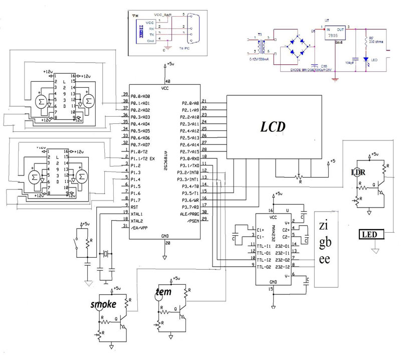 |