Gardening is one of the common hobbies. It keeps you close to nature. This is the healthiest hobby anyone can have. However, plants and trees are like pets. They need continuous care without breaking down . You need to be with them all the time . This is not always possible. You may need to go on vacation or business trips or travel for other reasons. At such times, the garden may remain unattended for some time or may even be left unattended for a long period of time. This project aims to take care of the garden alone with the help of electronics. This will eliminate unnecessary obligations and also make gardening easier.
This project is a garden monitoring and automation system. It is built using AVR Microcontroller and a bunch of electronic sensors. The AVR controller used in the circuit is ATmega16 . The ATmega16 continuously monitors soil moisture with the help of Soil Moisture Sensor and controls a water pump (here DC Motor for demonstration purposes) as the soil dries. The controller also tracks the ambient temperature with the help of LM35 Temperature Sensor and turns on the water pump as the temperature increases. The ATmega16 can also control garden lighting. It tracks whether it is day or night with the help of a Light Dependent Resistor . If it is night, it monitors whether anyone enters the garden with the help of Infrared sensors . It tracks number of visitors using IR sensors and turning on LED lights according to the number of occupants in the garden. The controller is also interfaced with a 16X2 character LCD where it displays the current temperature and soil moisture percentage of the LM35 and the Soil Moisture Sensor, respectively.
The controller is programmed using embedded C. AVR Studio 4 is used to write, edit and compile code for ATmega16. This project makes a garden fully automated and self-care . It also saves electricity by only controlling the pump when water is needed in the garden.
Required component –
ATmega16 microcontroller – 1
LCD display 16×2 – 1
Infrared module – 2
LM32-1
Soil moisture sensor – 1
LDR – 1
16MHz crystal oscillator – 1
LEADED – 4
5v Relay – 1
2N2222 – 1
1K resistant – 3
10 mil resistant – 1
22pf capacitor – 2
10 thousand potentiometer – 1
AVR Programmer – 1
PCB / Breadboard – 1
7805 – 1
Power supply – 1
Connecting wire – as required
Block Diagram:-
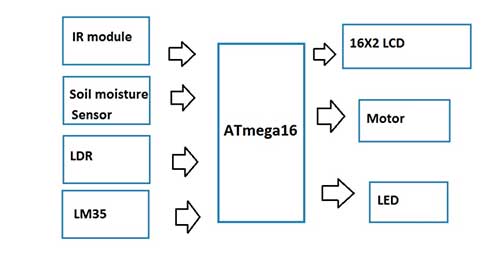
Fig. 1: Block diagram of garden monitoring and automation system based on AVR ATmega16
Circuit Diagram –
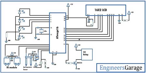
Fig. 2: Circuit diagram of AVR ATmega16 based garden automation and monitoring system
Prerequisite skills –
Before attempting this project, the developer must have the following prerequisites:
1) The developer must have basic knowledge of AVR Microcontrollers .
2) The developer must be familiar with programming in AVR Studio 4 .
3) Developer should know how LCD 16X2 is interfaced with AVR controller and text is displayed on it.
4) Developer must know how to control DC motor using AVR microcontroller .
5) The developer must have understanding of working with the AVR controller's internal ADC .
Circuit Connections –
The circuit of this project is based on the AVR ATmega16. All other components interface with the controller. The circuit is designed by assembling the following components –
1) AVR ATmega16 – Atmega16 is an 8-bit AVR Microcontroller with 32 I/O pins. It interfaces with sensors and character LCD to design the circuit of this project. ATmega16 has the following pin diagram –
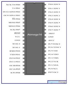
Figure 3: AVR ATmega16 microcontroller pin diagram
2) 16X2 Character LCD – A character LCD is connected to the controller to display the ambient temperature and soil moisture level. Character LCD VSS pin is connected to ground and VDD pin is connected to 5V DC. The RS, RW and E pins of the LCD are connected to bits 0, 1 and 2 of Port C of the ATmega16 respectively. The LCD interfaces in 4-bit mode to the AVR controller. Data pins D4, D5, D6 and D7 of the LCD are connected to bits 4, 5, 6 and 7 of Port C of the ATmega16 respectively.
3) LM35 Temperature Sensor – LM35 is a popular temperature sensor. The sensor has three terminals – VCC, Output and Ground. The VCC and Ground terminals are connected to 5 VDC and common ground, respectively. The output terminal is connected to bit 2 of Port A of the ATmega16.
4) Soil Moisture Sensor – The moisture sensor measures the volumetric water content of the soil with the help of a sensor probe that must be placed in the soil. The sensor module operates between voltages of 3.3 V to 5 V. It has an LM393 comparator on board. The module has four terminals – VCC, Ground, Data Out and Analog Out. The VCC and Ground pins are connected to the common VCC and Ground respectively. The sensor's analog output pin is connected to bit 1 of Port A of the AVR.
5) LDR sensor – LDR sensor is used to detect day or night in this circuit. The LDR sensor is a two-terminal light-sensitive resistor. It is connected as a voltage divider network at bit 0 of Port A of the ATmega16.
6) IR Sensors – There are two IR sensor modules used in the project. The two modules are used to detect Entry and exit of a visitor. Each sensor module is constructed from a pair of IR transmitter and IR receiver. The emitter is simply an IR LED and the detector is simply an IR photodiode that is sensitive to IR light of the same wavelength emitted by the IR LED. The sensor module has a digital output. The sensor module must generate HIGH logic or LOW logic so that it can be detected at the GPIO pin of the microcontroller. The analog output of the photodiode can be converted into digital data using Analog to Digital Converters (ADC). An operational amplifier is used to convert the analog output of the photodiode to digital logic LOW or HI. IR sensor modules have the following circuit diagram –
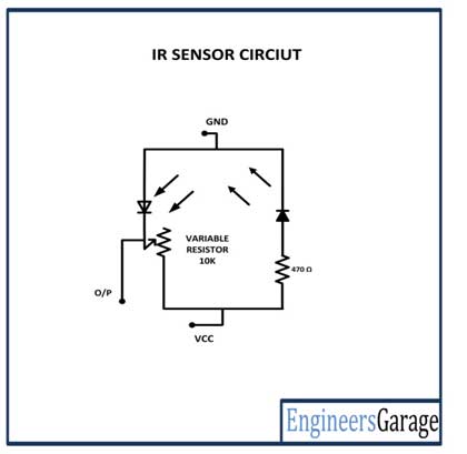
Fig. 4: IR Sensor Module Circuit Diagram
To make the sensor module, the IR transmitters are connected in series with 470 ohm pull-up resistors between VCC and ground forward bias configuration. IR receivers are connected in series with variable resistors between VCC and ground in reverse bias configuration forming a voltage divider circuit. The output of the IR receivers (photodiodes) is taken from the junction of the cathode terminals of the IR receiver and the variable resistors. This IR receiver and transmitter pair is connected between VCC and ground to form the IR sensor module. The output of the IR receivers is connected to bits 3 and 4 of Port A of the ATmega16 via the OPAM comparator. LM358M can be used as OPAMP comparator.
7) LEDs – There are 4 LEDs interconnected in bits 0, 1, 2 and 3 of Port B of the ATmega16. These LEDs are for demonstration purposes to show lighting control in the garden. In a practical version of the circuit, there could be LED lights controlled via relays by the controller.
8) DC Motor – A DC motor is connected to bit 5 of Port D of the AVR. This motor is for demonstration purposes to show the control of water pump by the controller. In a practical version of this circuit, there could be a real water pump which can be connected to the controller with the help of a 6V relay.
9) Power supply – The circuit can be powered by a battery and a 5V regulator IC like 7805. It can also be powered by AC mains using a step down Transformer and rectifier circuit with 7805 voltage regulator.
First of all, you need to load the hexadecimal code into the ATmega16 using the AVR programmer. The circuit can then be assembled on a breadboard or soldered onto a printed circuit board. It will be best to test on a breadboard first.
How the circuit works –
When the microcontroller is powered by a 5V DC source, it first flashes some initial messages on the LCD screen such as “Engineers Garage” and “WELCOME TO GARDEN MONITORING”. After these messages flash on the LCD screen once, the controller reads the analog voltages from the Soil Moisture Sensor and the LM35 Temperature Sensor . It converts analog voltages to digital values using integrated 10-bit ADC channels. The digitized readings are converted by the code into measurements in real physical quantities, i.e. percentage of soil moisture and ambient temperature, and then displayed on the character LCD.
If the humidity level detected by the humidity sensor drops below a threshold level, the controller turns on the engine to pump water into the garden. Water is supplied to different parts of the garden with the help of a drip kit. Likewise, if the ambient temperature rises above a threshold level, the controller turns the engine back on to pump water into the garden. Then the garden temperature can be cooled .
This garden monitoring system also controls garden lighting. It tracks day or light with the help of LDR sensor. If it is night, it detects entry and exit of any visitor with the help of two IR sensor modules. If a person enters the garden at night , it turns on an LED. If another person enters, another LED lights up. Similarly, other LEDs are lit. Similarly, if number of occupants in the garden is reduced by one or more occupants leaving , the LEDs are similarly turned off according to the number of current occupants in the garden.
The ATmega16 detects the analog voltage from the humidity sensor and the temperature sensor and converts them into digital readings using integrated ADC channels. ATmega16 has 10-bit ADC resolution, so it can convert voltage readings to a value between 0 and 1023.
2n -1 = 2 10 -1 = 1023
It has 8 ADC channels that have input on pins 0 to 7 of Port A. The operation of this circuit is based on the ADC feature of the microcontroller. Atmega16 has the following internal registers associated with the integrated ADC feature –
1) ADMUX (ADC multiplexer selection register)
2) ADCSRA (ADC Status and Control Register)
3) ADCL and ADCH (ADC data records)
4) SFIOR (IO special function register)
The operation of the ADC channels is controlled by the ADMUX register on the Atmega16. The ADMUX register has the following bit values –

Fig. 5: AVR ATmega16 ADMUX register bit values
The REFS1 and REFS0 bits are used to select the voltage reference. The voltage reference is selected according to the following bit values of REFS1 and REFS0 –
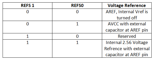
Here, AVCC with external capacitor in AREF pin mode is selected, for which REFS0 is set to 1 and REFS1 is set to 0. As REFS1 is zero by default, only REFS1 needs to be modified as follows –
ADMUX = (1<
The ADLAR bit affects the presentation of the ADC conversion result in the ADC Data Register. When writing 1 in ADLAR, the conversion result is adjusted. Otherwise, the result will be adjusted correctly.
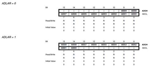
Fig. 6: Changing bits of ADC data registers according to the status of the ADLAR bit in the ADMUX register
Bits MUX4 to MUX0 are used to select analog channel, input type and gain. The input channel and gain selection is done as follows –
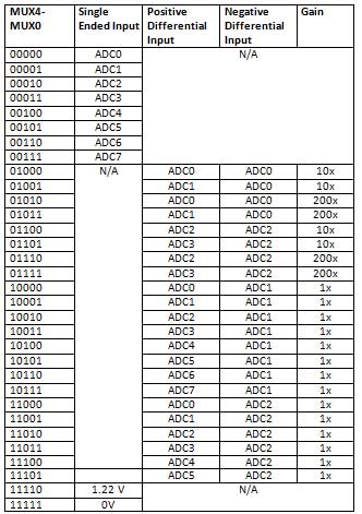
Here ADC Channel 3 is selected by setting MUX0 to 1 and MUX1 to 1 as follows –
ADMUX = (1<
ADCSRA has the following bit values –
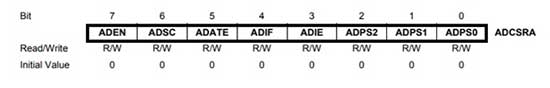
Figure 7: AVR ATmega16 ADCSRA register bit values
The ADEN bit is used to enable ADC . Bits ADPS2, ADPS1, ADPS0 are used to determine the division factor between the XTAL frequency and the ADC input clock. The ADSC bit is used to start each conversion in single conversion mode and to start the first conversion in free-running mode. The ONE ENCOUNTER part is used to activate automatic shooting. The ADIF bit is set when an ADC conversion is complete and data registers are updated. The ADIE bit is used to enable interrupt when conversation is complete. Here the ADC control register is defined as follows –
ADCSRA = (1<
The SFIOR register is used for automatic triggering. This record is not used in the programming of this project.
Programming guide –
This system is based on the AVR ATmega16. It is programmed in embedded C using AVR Studio 4. Other programming tools like Atmel Studio or Notepad++ can also be used to write and compile the code. First of all, user needs to add LCD library provided below in zip file, copy and paste the code into AVR Studio 4 to generate hex file.
Here, ATmega16 is used to detect the condition of garden and take appropriate action to control gardening equipment like motor and lights. The LCD is interfaced with the atmega16 to monitor the value of ambient temperature and soil humidity through sensors.
Constants used in the code: –
#define F_CPU 16000000UL: – Constant used to define the MCU clock frequency
#define IR1 0b00001000: – IR sensor 1 is connected to pin 4 of PORTA
#define IR2 0b00010000: – IR 2 sensor is connected to pin 5 of PORTA
Variable used in code: –
int num_LDR ; : – To get ADC value from LDR
int num_Moist ; : – To get ADC value from soil moisture sensor
int num_temp; : – To obtain the temperature v
int person=0 ; : – To Count the number of people entered or left
int moist_per ; : – To calculate humidity in percentage
int temp_c; :- To calculate temperature in Celsius
character LDR(5) ; : – To print LDR value on LCD
char Wet(5) ; : – To print soil moisture percentage on LCD
character temperature (5) ; : – To print the LM35 value in Celsius on the LCD
Header file and libraries used in the code: –
#include
#include
#include
Functions used in the code: –
adc_init: – To initialize ADC on ATmega16
adc_read: – To read the ADC value on the selected channel
ir_count : – To count the person who entered/exited to control the LED
LCDinit : – To initialize the LCD
LCDclr: – To clean the LCD
LCD Cursor OFF: – To turn off the cursor
LCDGotoXY: – To map the cursor
LCDstring : – To print the String on the LCD
run: – Store value as character print on LCD
Algorithm:-
The code of this garden monitoring and automation system works according to the following algorithm –
1) When the circuit is turned on, firstly the Ports are initialized as input and output. Port A is defined as input by setting DDRA to 0x00. Port B and Port D are defined as output by setting DDRB and DDRD respectively to 0xff. Initially, all ports are set to LOW passing 0x00 for Port A, Port B and Port D.
 DDRA = 0x00;

 DDRB = 0xff;

 PORT = 0x00;

 PORTB = 0x00;

 DDRD = 0xff;

 PORTD = 0x00;
2) After that, the ADC is initialized by the adc_init function to activate the ADC operation on the ADC pins. The LCDinit function is used to initialize the LCD for LCD operations. When the LCD is on, it may have a garbage value, so the LCDclr function is used to clear the LCD and the cursor is turned off using the LCDcursoroFF function.
 adc_init;

 LCDinit;

 LCDclr;

 LCDcursorOFF ;
3) Here the LCD cursor is mapped to (3,0) which means first row and 3 third column. It is used to print “ENGINEERS” then the LCD cursor is mapped to (4,1) which is 2nd row and 4th column and “GARAGE” is printed. It takes some time after which the LCD is cleared using the LCDclr function.
 LCDGotoXY(3,0);

 LCDstring("ENGINEERS",9);

 LCDGotoXY(4,1);

 LCDstring("GARAGE",6);

_delay_ms(1500);

 LCDclr;
4) Now the LCD is ready to print next message. Therefore, the LCD cursor is set to (4,0) to print “WELCOME” and is again set to (6,1) to print “FOR”. After some delay it is cleared and a new massage “GARDEN”, “AUTOMATION” are printed according to the defined mapping. The message remains on the screen and after some delay, the final messages “Humidity =”, “Temperature =” are printed on the LCD with Sensor Outputs.
 LCDGotoXY(4,0);

 LCDstring("WELCOME",7);

 LCDGotoXY(6,1);

 LCDstring("TO",2);

 _delay_ms(1000);

 LCDclr;


 LCDGotoXY(5,0);

 LCDstring("GARDEN",6);

 LCDGotoXY(3,1);

LCDstring("MONITORING",10);

 _delay_ms(1500);

 LCDclr;


 LCDGotoXY(0,0);

 LCDstring("Moisture = %,15);

 LCDGotoXY(0,1);

 LCDstring("Temperature =",13);
5) Now the channel ADC sensor values are initialized into variables – num_LDR, num_Moist and num_temp. The Humidity and Temperature value are analogous in nature, therefore, they are mapped via formula. wet_per is used to calculate the humidity value in percentage and temp_c is used to calculate the temperature value in Celsius.
 num_LDR =adc_read(0);

 num_Moist =adc_read(1);

 num_temp =adc_read(2);


 moist_per=((float)num_Moist/1023*100);

moist_per=100-moist_per;

 temp_c=((float)num_temp/1023*5*100);
6) Now the LCD cursor is mapped to (10,0) to print the moisture percentage. After that, the LCD cursor is mapped to (13,1) to print the temperature value in Celsius.
 LCDGotoXY(10,0);

 sprintf (Moist,"%d ",moist_per);

 LCDstring (Moist, strlen (Moist));

 LCDGotoXY(13,1);

 sprintf (temp,"%dc ",temp_c);

 LCDstring (temp, strlen (temp));
7) There are two conditions added for the humidity sensor – a) when the percentage is less than 30, pin 5 of port D will be where relay is connected and it will turn off when the humidity value exceeds 70 percent. After that, there is a condition for LDR to detect light or dark. If the LDR value is below 500 in terms of ADC, then it is dark outside, then the ir_count function will be called, which will turn on the light according to the number of people entered/exited in garden .
 if (moist_per<30)

 {

 PORTD = (1<<PD5);

 }

 if(moist_per>70)

 {

 PORTD &= ~(1<<PD5);

 }


if(num_LDR<500)

 ir_count;

 else

 PORTB &= ~0x0f;
Check out the full code and try this project now.
Project source code
###
//Program to /* * Garden_monitoring.c * * Created: 11/3/2019 10:45:12 AM *Author: Administrator */ #define F_CPU 16000000UL #include#include #include #define IR1 0b00001000 #define IR2 0b00010000 char LDR(5),Moist(5),temp(5); int num_LDR,num_Moist,num_temp; int person=0; int moist_per,temp_c; uint16_t adc_read(uint8_t ); void adc_init; void ir_count; int main(void) { DDRA = 0x00; DDRB = 0xff; PORT = 0x00; PORTB = 0x00; DDRD = 0xff; PORTD = 0x00; adc_init; LCDinit; LCDclr; LCDcursorOFF ; LCDGotoXY(3,0); LCDstring("ENGINEERS",9); LCDGotoXY(4,1); LCDstring("GARAGE",6); _delay_ms(1500); LCDclr; LCDGotoXY(4,0); LCDstring("WELCOME",7); LCDGotoXY(6,1); LCDstring("TO",2); _delay_ms(1000); LCDclr; LCDGotoXY(5,0); LCDstring("GARDEN",6); LCDGotoXY(3,1); LCDstring("MONITORING",10); _delay_ms(1500); LCDclr; LCDGotoXY(0,0); LCDstring("Moisture = %,15); LCDGotoXY(0,1); LCDstring("Temperature =",13); while (1) { num_LDR =adc_read(0); num_Moist =adc_read(1); num_temp =adc_read(2); moist_per=((float)num_Moist/1023*100); moist_per=100-moist_per; temp_c=((float)num_temp/1023*5*100); LCDGotoXY(10,0); sprintf(Moist,"%d ",moist_per); LCDstring(Moist,strlen(Moist)); LCDGotoXY(13,1); sprintf(temp,"%dc ",temp_c); LCDstring(temp,strlen(temp)); if (moist_per<30) { PORTD = (1< 70) { PORTD &= ~(1< ###
Circuit diagrams
| AVR-ATmega16-Garden-Monitoring-System-Circuit-Diagram-1 | 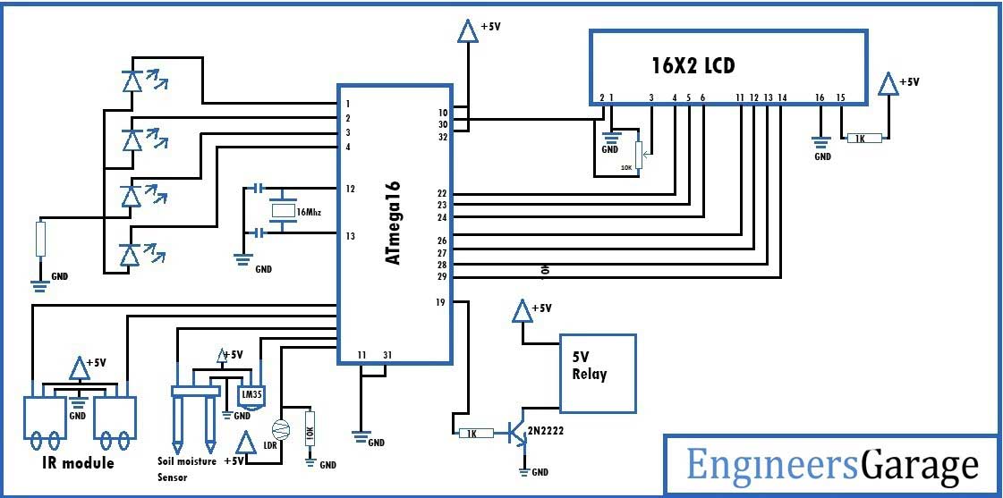 |