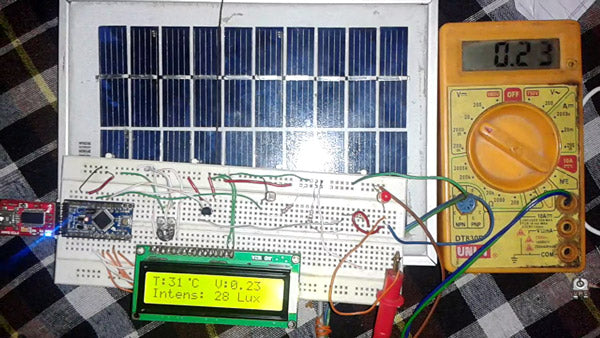
There are Power Stations for Maintenance or Monitoring of Power Circuits or Parameters related to the Solar Panel. Parameters like Voltage, Temperature, Light Intensity and Current which are important to monitor. Monitoring these parameters is also important in households. So, here we discuss how to monitor solar panel parameters. For this project the reader must have knowledge about how to start with Arduino and LCD Interface with Arduino .
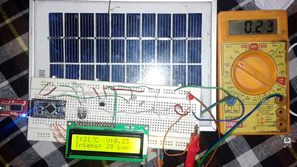
Figure 1: Arduino-based solar panel electrical parameter monitor prototype
In this circuit all parameters are in analog form. We just need to convert them to DigitalfForm and display these digital values on the LCD. Some additional circuitry is also required for proper measurement.
Figure 2: Arduino-based solar panel electrical parameter monitor block diagram
Voltage Measurement
Measuring the voltage of the solar panel is very easy, it can reach 5 volts. But if we want to measure more than 5 volts, we will have to use some additional circuits like Voltage Divider. This circuit changes according to Voltage, which means How Much Voltage do we have to Measure.
Suppose if we want to measure 5 volts, there will be no need for any additional circuit. Just connect the solar panel output voltage to the Arduino analog pin and convert it into a digital result and display it on the LCD or computer.
And suppose if you want to measure up to 10 volts then you have to use the given circuit.
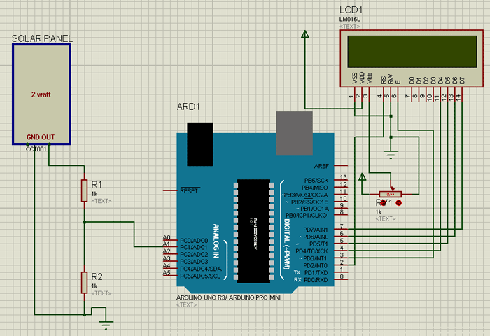
Figure 3: Arduino-based digital voltmeter circuit diagram
To measure voltage we have to follow the given formula:
Voltage = (Analog value / resistor factor) * Reference voltage
Where:
Analog value = voltage divider analog output
Resistor factor = 1023.0/(R2/R1+R2)
Reference voltage = 5 volts
And let's assume:
R1 = 1K
R2=1K
Resistor factor= 1023.0 * (1000/1000+1000)
Resistor factor = 1023.0 * 0.5
Resistor factor = 511.5 for up to 10 volts and for more see the table provided.
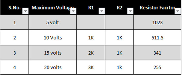
Figure 4: Table showing resistor relationships for voltage measurement
Light intensity measurement
Light Intensity is also easy to implement in the project, as is Voltage Measurement. For the light intensity first we have to use the voltage divider and then measure the voltage. Later, through some calculations, we will obtain the Result of the Light Intensity.
Here we will show you how to do it:
For this we have to use the LDR, (Light Dependent Register) which is very common and easily available on the market.
Now you can see the Circuit Diagram for Light Intensity Measurement part.
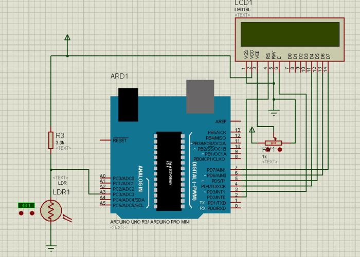
Figure 5: Circuit diagram of Arduino based light intensity meter
Here we are using a 3.3K ohm resistor and an LDR connected together and the midpoints are used as the output. As light falls on the LDR, the resistance of the LDR decreases, due to which Analog Voltage is generated, later apply this Voltage to the Arduino.
The relationship between RL (LDR) and light intensity (Lux) is given below:
R$=500/Lux
The output voltage of this circuit can be calculated using the given formula.
Vout= 5 * RL / (RL+3,3)
Where RL is the load resistance (LDR resistance varies according to light intensity).
Now, using the given formula, we can calculate the light intensity in lux (where lux is the unit of light intensity).
Lux= (2500 / Vout – 500) / 3.3
Temperature, circuit and component measurement
Temperature measurement
To measure temperature here we use lm35 which provides 10 mV for every 1 degree Celsius. The circuit is simple for this.
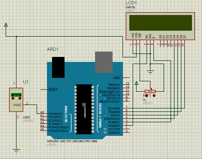
Figure 6: Arduino-based digital thermometer circuit diagram
Using the given formula, we can calculate the temperature in degrees Celsius:
Temperature=Analog value*(5.0/1023.0)*100;
Where, 5 is the reference voltage.
The circuit
LCD connections are shown on the circuit. See the circuit diagram guide for the circuit.
Components used
1. Arduino
2. Solar Panel
3.LM35
4. LDR
5.LCD 16×2
6. Resistors
7. Connecting wires
8. Power supply
Project source code
###
/*-----------Solar energy measurement Using Arduino---------*/ /*--------------------By Saddam Khan-----------------------*/ /*-------------------Engineers Garage----------------------*/ #include#define sensor A0 #define VOLT A1 #define LUX A3 LiquidCrystal lcd(2,3,4,5,6,7); float Temperature, temp, volt, volts,lux,Temp; int temp1, value; byte degree(8) = { 0b00011, 0b00011, 0b00000, 0b00000, 0b00000, 0b00000, 0b00000, 0b00000 }; void setup { lcd.begin(16,2); lcd.createChar(1, degree); Serial.begin(9600); lcd.setCursor(0,0); lcd.print(" Soler Energy "); lcd.setCursor(0,1); lcd.print(" Measurement "); delay(2000); lcd.clear; lcd.setCursor(0,0); lcd.print(" By Saddam Khan "); lcd.setCursor(0,1); lcd.print("ENGINEERS GARAGE"); delay(2000); lcd.clear; } void loop { /*---------Temperature-------*/ float reading=analogRead(sensor); Temperature=reading*(5.0/1023.0)*100; delay(10); /*------------Voltage----------*/ temp1=analogRead(VOLT); volts= (temp1/511.5)*5; delay(10); /*-----Light Intensity------*/ value=analogRead(LUX); volt=(value/1023.0)*5; lux=((2500/volt)-500)/3.3; delay(10); /*------Display Result------*/ lcd.clear; lcd.setCursor(0,0); lcd.print("T:"); lcd.print((int)analog_value); lcd.write(1); lcd.print("C"); lcd.setCursor(8,0); lcd.print("V:"); lcd.print(volts); lcd.setCursor(0,1); lcd.print("Intens: "); lcd.print((int)lux); lcd.print("Lux"); Serial.println((int)Temp); Serial.println(volts); Serial.println((int)lux); delay(500); } ###
Circuit diagrams
| Circuit Diagram-Arduino Based Solar Panel Based Electrical Parameters Monitor | 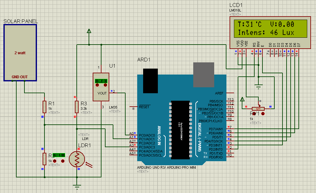 |

