The sensors use master-slave protocols to interface with microcontrollers and microcomputers. Among many different slave-master protocols, I2C and SPI protocols are the common serial communication protocols widely found in embedded devices. Both protocols allow the microcontroller/microcomputer to assume the role of master and allow the interface of several sensors and blocks embedded in a common bus. This tutorial will discuss implementing the I2C protocol in MicroPython and explore how sensors interface with ESP8266 and ESP32 using the I2C bus. Learn more about the I2C protocol before continuing this tutorial.
Machine Module
The MicroPython machine module is responsible for managing basic hardware resources of the supported ports. The module includes classes to control digital input/output, control output signals from external devices, pulse width modulation, analog to digital conversion, control peripherals ADC, UART, SPI, I2C, I2S, timer, RTC, Watchdog timer and SD card management. It has I2C class for managing the I2C bus of supported ports.
Class I2C
I2C is a two-wire protocol. It uses two lines – a data line (SDA) and a clock line (SCL). MicroPython implements I2C hardware and I2C software. I2C hardware uses the underlying I2C peripheral and supported port bus for serial communication according to the I2C protocol. Since I2C hardware peripherals are tied to specific pins on a port, I2C hardware implementation could be done only on those specific pins.
I2C hardware is implemented in the machine module I2C class. The I2C class is imported into a MicroPython script using the following statement.
of I2C machine import
After importing the I2C class, you need to instantiate an I2C object. A constructor function does this. The constructor function has the following prototype.
class machine.I2C(id, *, scl, sda, freq=400000)
The constructor function can receive four arguments – id, scl, sda and freq. The id is the identifier of the specific I2C peripheral. If a port has multiple I2C peripherals, it is important to pass the I2C ID. The id can be an integer, string or tuple. This depends on the specific port. The scl and sda are the pins used for the I2C clock and I2C data respectively. If the SCL and SDA pins can be changed on a port, these arguments can be passed to assign pins to available I2C peripherals. If scl and sda are not passed as arguments, the default pins will be assigned to I2C SCL and SDA respectively. The SDA and SCL pins can be fixed to many ports and cannot be changed. freq defines the maximum frequency for the I2C clock. Following are some valid examples of I2C builder.
i2c = I2C(0)
i2c = I2C(1, scl=Pin(5), sda=Pin(4), freq=400000)
i2c = I2C(scl=Pin(5), sda=Pin(4), freq=100000)
The I2C class includes the following methods for configuring and managing data communication.
I2C.init : This method is used to initialize the I2C bus. Applies to an I2C object, which is already instantiated with an I2c id. The init method can take sda, scl and freq as arguments.
I2C.deinit : This method turns off the I2C bus. It is only available on the WiPy port.
I2C.scan : This method scans all I2C addresses between 0x08 and 0x77 and returns a list of responding addresses. This method is useful for listing connected I2C devices. Devices are recognized by their I2C addresses.
I2C.readfrom(addr, nbytes, stop=True) : This method reads nbytes from the I2C address . A stop condition will be generated upon completion of the read operation if the stop is true. A call to this method returns an object of type byte, which must be stored in a variable.
I2C.readfrom_into(addr, buf, stop=True) : This method reads the I2C buffer from the I2C address . The method returns nothing, but all bytes available on the I2C bus for reading are saved. The stop condition is created after reading into the buffer if the stop is true.
I2C.writeto(addr, buf, stop=True) : This method writes bytes from the buffer to the I2c address . It returns the number of confirmations received. If no acknowledgment is received after sending a byte, the remaining bytes will not be sent. If stop is true, the stop condition is generated after the bytes are sent.
I2C.writevto(address, vector, stop = True) : This method sends bytes stored in a vector to the I2C address . A vector is a list or tuple of objects with a buffer protocol. Using this method, multiple objects can be sent to a given I2c address with a single call. The method returns the number of confirmations received. The method sends the address once, and then the byte objects are sent sequentially. The remaining bytes and objects will not be sent if acknowledgment is not received after sending a byte. If stop is true, the stop condition is generated after sending the vector.
I2C.start : This method generates a start condition on the I2C bus. SDA is pulled LOW in the starting condition while SCL is pulled HIGH.
I2C.stop : This method generates a stop condition on the I2C bus. The SDA is pulled HIGH in the stop condition while the SCL is pulled LOW.
I2C.readinto(buf, nack=True) : This method is used to read bytes from the bus and store them in the buffer. The number of bytes read is equal to the buffer size. After all bytes have been received, confirmation will be sent; otherwise, no confirmation will be sent as long as nack is set to true.
I2C.write(buf) : This method is used to write buffer bytes to the I2C bus. The method returns the number of confirmations received. It is equal to the number of bytes written to the bus successfully. After sending each byte, confirmation is received. If no acknowledgment is received, the remaining bytes will not be written.
I2C.readfrom_mem(addr, memaddr, nbytes, *, addrsize=8) : This method is used to read bytes from the I2C address starting from the memory address memadr . Address size specifies the size of the memory address in bits. The number of bytes read is equal to nbytes . The method returns a byte object.
I2C.readfrom_mem_into(addr, memaddr, buf, *, addrsize=8) : This method is used to read bytes into the buffer buffer of the I2C address starting from the memory address memadr . Address size specifies the size of the memory address in bits. The number of bytes read is equal to the buffer size.
I2C.writeto_mem(addr, memaddr, buf, *, addrsize=8) : This method is used to write a buffer buffer to the I2C address starting from the memory address memadr . The method returns nothing. Address size specifies the size of the memory address in bits.
I2C Software in MicroPython
I2C software is implemented in MicroPython using the SoftI2C class. The SoftI2C class is imported into a MicroPython script using the following statement.
SoftI2C machine import
After importing the SoftI2C class, it is necessary to instantiate an I2C object. A constructor function does this. The constructor function has the following prototype.
class machine.SoftI2C (scl, sda, freq = 400000)
All the methods available in the I2C class are also available in the SoftI2C class as is. I2C software is implemented using bit banging. It can be generated on any GPIO with output capability. It is important to note that I2C software is not as efficient compared to I2C hardware. It is possible to communicate with multiple I2C devices on the same I2C bus, as long as each device connected to the bus has a different I2C address. Therefore, even if only one hardware I2C peripheral is available on a port, it must be used for I2C communication. I2C software should only be a last resort.
I2C on ESP8266
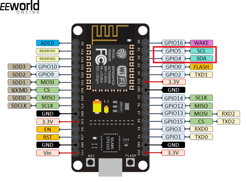
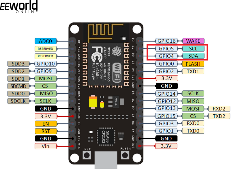
There is a single I2C driver in ESP8266. This driver is implemented in software and is available on all GPIOs. Since the software implementation of ESP8266 I2C is internal, the MicroPython I2C class (written for I2C hardware) is used to manage I2C communication on the ESP8266. The standard I2C pins on the ESP8266 are GPIO4 (SDA) and GPIO5 (SCL).

Following is a valid example of using I2C class for data communication in ESP8266.
Pin machine import, I2C
i2c = I2C(scl=Pin(5), sda=Pin(4), freq=100000)
i2c.readfrom(0x3a, 4)
i2c.writeto(0x3a, '0xFF')
I2C hardware on ESP32
There are two hardware I2C peripherals in the ESP32. These peripherals are identified by ids – 0 and 1. The default SDA and SCL pins for I2C0 are GPIO19 and GPIO18, respectively. The default SDA and SCL pins for I2C1 are GPIO26 and GPIO25, respectively. However, any GPIO with output capability can be used as SDA and SCL lines on the ESP32. Following is a valid example of using I2C hardware in ESP32.
Pin machine import, I2C
i2c = I2C(0)
i2c.readfrom(0x3a, 4)
i2c.writeto(0x3a, '0xFF')
The following example shows the use of non-standard pins for I2C hardware.
Pin machine import, I2C
i2c = I2C(0, scl=Pin(5), sda=Pin(4), freq=400000)
i2c.readfrom(0x3a, 4)
i2c.writeto(0x3a, '0xFF')
I2C Software on ESP32
The I2C software can be used on any GPIO on the ESP32 with output capability. Learn more about GPIO availability on the ESP8266 and ESP32. Following is a valid example of using I2C software on ESP32.
Machine Import Pin, SoftI2C
i2c = SoftI2C(scl=Pin(5), sda=Pin(4), freq=100000)
i2c.readfrom(0x3a, 4)
i2c.writeto(0x3a, '12')
buf = bytearray(3)
i2c.writeto(0x3a, buf)
ADXL345 interface with ESP8266 using I2C bus
Now that you are familiar with implementing the I2C protocol in MicroPython, let's get our hands dirty. Sensors typically use I2C and SPI protocols to interface with embedded controllers and microcomputers. Let's interface an ADXL345 accelerometer sensor with ESP8266 using the MicroPython implementation of the I2C protocol.
Required components
- ESP8266/ESP32 x1
- ADXL345 x1 accelerometer sensor
- Breadboard x1
- Connecting wires/jumper wires
- Micro USB cable x1
Circuit Connections
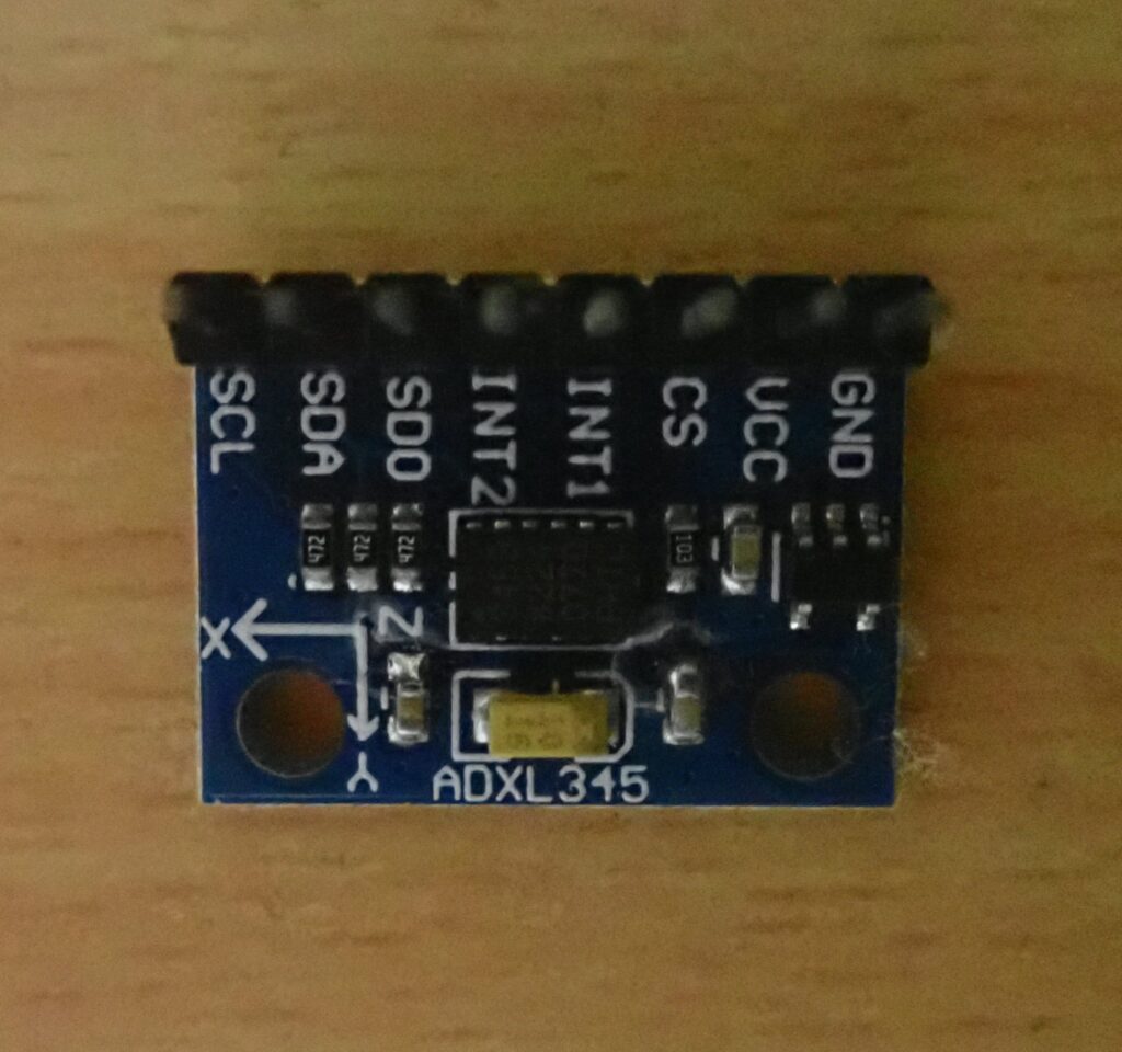
The ADXL345 accelerometer sensor can be interfaced with ESP8266 or ESP32 using I2C or SPI protocols. Typical ADXL345 accelerometer sensor breakout boards have pinouts for both interfaces or just the I2C bus. A breakout board exposing only the I2C bus for interfacing with ADXL345 is shown in the image below.

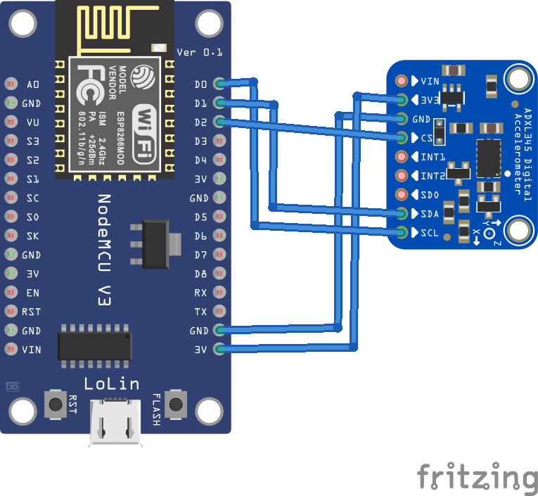
Connect the VCC and Ground pins of the ADXL sensor with the 3V and GND output of the ESP8266, respectively. Connect the SCL, SDA and CS pins of the ADXL345 breakout board with the D0 (GPIO16), D1 (GPIO5) and D2 (GPIO4) pins of the ESP8266. Note that the standard I2C pins on the ESP8266 board are D1 (SCL) and D2 (SDA). However, we can use any GPIO with output capability on the ESP8266 for SDA and SCL lines. We choose D0 for SCL and D1 for SDA.

Note that you must have loaded the MicroPython firmware for ESP8266 and be ready for the uPyCraft IDE before continuing this project.
MicroPython Script
About the ADXL345 accelerometer
ADXL345 is a 3-axis MEMS accelerometer sensor. It is a digital inertial sensor and uses a capacitive accelerometer design. It has a user selectable range of up to +/- 16g, a maximum output resolution of 13 bits, a sensitivity of 3.9 mg/LSB and a maximum output data rate of 3200 Hz. The sensor has I2C and SPI interfaces to communicate with controllers/computers. ADXL345 measures static acceleration due to gravity as well as dynamic acceleration resulting from motion or shock. It can be used to detect linear acceleration in 3 axes and detect the tilt and free fall of an object. It can detect the presence or lack of relative motion by comparing acceleration values to user-defined thresholds.
The ADXL345 has built-in registers that can be read and written to configure sensor settings and read acceleration values. ADXL345 offers four measurement ranges: +/-2g, +/-4g, +/-8g and +/-16g. The default measurement range is +/-2g, which can detect acceleration of up to 19.6 m/s2 in any direction along each axis. Maximum resolutions are 10 bits for +/-2g, 11 bits for +/-4g, 12 bits for +/-8g, and 13 bits for the +/-16g range. The default resolution is 10 bits, which for the +/-2g range (default) allows a sensitivity of 3.9mg/LSB. The default data rate is 100 Hz. All of these settings can be changed or configured by writing data to the ADXL345's built-in registers. A controller/computer can read the acceleration by reading values from registers 0x32 to 0x37.
How it works
ADXL345 communicates with the microcontroller via I2C or SPI. The ADXL345 breakout board exposes only I2C lines for data communication with the sensor. ADXL345 has an ALT address pin that can be connected to set the I2C address of this digital sensor. If the ALT ADDRESS pin is pulled high on a module, the 7-bit I2C address for the device will be 0x1D, followed by the R/W bit. This translates to 0x3A for writing and 0x3B for reading. If the ALT ADDRESS pin is connected to ground, the 7-bit I2C address for the device is 0x53 (followed by the R/W bit). This translates to 0xA6 for writing and 0xA7 for reading. The ALT ADDRESS pin is already pulled up or down on a module. The I2C address of the ADXL345 sensor used in this tutorial is 0x53. This is confirmed by scanning the I2C bus using the i2c.scan method of the MicroPython I2C class.
The ADXL345's internal registers need to be read and written to configure settings (such as defining measuring range, data transfer rate, sensitivity and resolution) and reading acceleration values. A table of these records is provided below.
To communicate with ADXL345, firstly, its configuration parameters are defined by writing to registers – DATA_FORMAT (0x31), BW_RATE (0x2C), POWER_CTL (0x2D), INT_ENABLE (0x2E), OFSX (0x1E), OFSY (0x1F), and OSFZ ( 0x20). After writing to the configuration registers via I2C protocols, acceleration along the x-axis is obtained by reading registers 0x32 and 0x33 on the I2C bus. Acceleration along the y-axis is obtained by reading registers 0x34 and 0x35 on the I2C bus. Acceleration along the z axis is obtained by reading registers 0x36 and 0x37 on the I2C bus.
Read acceleration values are 16 bits. The values obtained from the register pairs are converted into a single 16-bit, 2's complement value to obtain the final raw acceleration values. These values are multiplied by a factor of 3.9, corresponding to a resolution of +/-4g, to obtain acceleration values in mg.
The code
The MicroPython code starts with importing the Pin and I2C classes from the machine module. The time module is imported to provide delay and the ustruct module is imported to format acceleration values to 16 bits.
Below is the definition of constants that represent the ADXL345 configuration registers. The SCL, SDA and CS pins for the I2C bus are defined and the CS pin is defined as a digital output. An I2C object is instantiated by setting D0 (GPIO16) and D1 (GPIO5) to SCL and SDA, respectively, and setting the maximum I2C frequency to 10,000 Hz. The I2C bus is scanned by calling the i2c.scan method, and the list returned is stored in a list 'slv'. With the help of a for loop, the values in the 'slv' list are compared with the known I2c address of the ADXL345. A message showing “ADXL345 was found” will be printed on the console if the address is found. The corresponding address is stored in a variable 'slvAddr'.
A 'writeByte' function is defined to write bytes to the ADXL345 via the I2C bus. A 'readByte' function is defined to read bytes from the ADXL345 over the I2C bus. The writeByte function is used to write data to the configuration registers – DATA_FORMAT, BW_RATE, INT_ENABLE, OFSX, OFSY, OFSZ and POWER_CTL.
In an infinite while loop, the values of registers 0x32 and 0x33 are read by calling the user-defined readByte function. Values are formatted to a single 16-bit number using the ustruct.unpack method. This gives the raw value of the acceleration along the x-axis. The raw value is multiplied by 3.9 to obtain the acceleration in mg.
Similarly, values from registers 0x34 and 0x35 are taken to derive the acceleration along the y-axis. The values from registers 0x36 and 0x37 are taken to derive the acceleration along the z axis. The loop continues indefinitely until the script ends in uPyCraft or Thonny IDE.
Result

