
The first step in programming embedded devices is to perform digital input/output. Digital input/output refers to reading parallel data. The same logic signals are used for switching and control operations. MicroPython, an embedded firmware, essentially includes libraries to control digital input/output and other hardware functions. MicroPython can be loaded and run on a variety of hardware platforms, namely microcontrollers. These microcontrollers are called gates in MicroPython terminology. Each port has its own hardware features, integrated peripherals, and pin configuration. Although MicroPython supports several different microcontroller systems, it has a universal syntax for all hardware functionalities. In this article, we will discuss how we can read digital input and generate digital output using MicroPython. As we will test our MicroPython codes on ESP8266 and ESP32, we will familiarize ourselves with both boards and show how the digital input/output works.
Even simple digital input/output operations involve solid technical knowledge. To learn about the technical aspects of digital input in microcontrollers and have in-depth knowledge of LEDs, check out our article on digital input on Arduino. To learn more about switches and technical aspects of digital output on microcontrollers, we recommend reading our article on digital output on Arduino. You are expected to be familiar with what MicroPython is. And yes, before trying hands-on digital input/output on ESP8266/ESP32 using MicroPython, you should upload MicroPython firmware on ESP8266/ESP32 and prepare with uPyCraft/Thonny IDE on your computer.
MicroPython Machine Library
MicroPython provides the machine module for several specific functions related to the microcontroller hardware. The module contains classes to control digital input/output, control output signals from external devices, pulse width modulation, analog to digital conversion, control peripherals ADC, UART, SPI, I2C, I2S, timer, RTC, Watchdog timer and SD card management. The module is designed to directly access different hardware blocks of multiple microcontrollers without any restrictions. In addition to classes related to specific hardware functions, the module provides methods for enabling/disabling interrupts, power management, reset and bootloader. Typically, only the required module classes are imported into a MicroPython script to keep the code short and clean.
PIN class in machine library
The machine module PIN class is designed to control general purpose inputs/outputs (GPIO microcontroller). This class is imported into a MicroPython script using the following statement.
Machine Import Pin
The pin class contains methods for setting the pin mode and getting and setting the logic levels of digital pins. Each port (compatible microcontroller) has a different configuration and pin assignment. A physical pin of a port is defined by an identifier, that is, a variable. The identifier is an instantiation of the Pin object. A specific physical pin of a port/microcontroller is specified by a number, string, or tuple ID in the instantiation of the pin object. The id is specific to a particular port/microcontroller. Pin instantiation is done by the class's Pin method. This method is defined as follows.
class machine.Pin(id, mode=- 1, pull=- 1, *, value=None, drive=0, alt=- 1)
The Pin method parameters are described below.
ID : The required parameter identifies a specific physical pin on a given port/microcontroller. The id can be provided as a number, string or tuple.
mode : specifies the pin mode of the specified pin. The mode is specified by the following constants – Pin.IN, Pin.OUT, Pin.OPEN_DRAIN, Pin.ALT, Pin.ALT_OPEN_DRAIN, Pin.ANALOG. If the mode is set to Pin.IN, the pin will be configured for digital input. For external devices, this pin is in high impedance state. If the mode is set to Pin.OUT, the pin will be configured for digital output. If the mode is set to Pin.OPEN_DRAIN, the pin will be configured for open drain output. This means that if the pin is set to 0, it will be active LOW. If set to 1, it enters a high impedance state where it is in a floating state until pulled down or up by an external circuit. Not all ports/microcontrollers support open drain output. If the mode is set to Pin.ALT, the pin will be configured for alternative functions such as SPI, I2C or UART functions assigned to it on a given port. Pin.ALT_OPEN_DRAIN mode is the same as Pin.ALT, except that it sets the open-drain pin. If the mode is set to Pin.ANALOG, the pin will be configured for analog input.
pull : Specifies the internal pull-up/pull-down when the pin is configured as input. It is specified by the following constants – None, Pin.PULL_UP and Pin.PULL_DOWN. If pull is set to None, neither the pull-up nor the pull-down resistor will be enabled. If pull is set to Pin.PULL_UP, the pull-up resistor will be enabled on the specified pin. If pull is set to Pin.PULL_DOWN, the pull-down resistor will be enabled on the specified pin.
value : Specifies the signal level of the pin if its mode is set to OUT or OPEN_DRAIN. If set to 0, the output signal is LOW. If set to 1, the output signal will be set to HIGH.
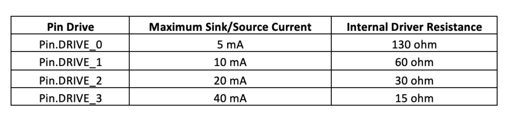
drive : Specifies the output power or output current-carrying capacity of a given pin. It can be set as Pin.DRIVE_0, Pin.DRIVE_1, Pin.DRIVE_2 or Pin.DRIVE_3, corresponding to the rising output power as mentioned in the table below.
 For example, the following instruction defines pin 2 of a given port as a digital output.
p2 = Pin (2, Pin.OUT)
Similarly, the following instruction defines pin 1 of a given port as a digital input with internal pull-up enabled.
p1 = Pin (1, Pin.IN, Pin.PULL_UP)
Unlike typical microcontroller programming, MicroPython allows you to change the mode and other parameters of a pin mid-program. This is done by resetting the pin using the Pin.init method. This method is defined as follows.
Pin.init(mode=- 1, pull=- 1, *, value=None, drive=0, alt=- 1)
The parameters of the Pin.init method are specified in the same way as in the Pin method. The mode of a pin object can also be set explicitly by calling the Pin.mode method. If Pin.mode is called without arguments, it returns the current mode of the given pin. Similarly, the Pin.pull method allows you to set or get the pin's pulling state, and Pin.drive allows you to get or set the pin's drive force.
The digital logic on a given pin is obtained or set using the Pin.value method. It is defined as follows.
Pin.value((x))
If called without arguments, returns the digital logic level of the pin. If the pin is set to Pin.IN, it will return the actual input value currently present on the pin. If the pin is set to Pin.OUT, it returns an undefined value. If the pin is set to Pin.OPEN_DRAIN, it will return an undefined value if set to 0, otherwise it will return the actual input value currently present on the pin if set to 1. If Pin.value is provided with an argument, it must be a boolean, i.e. true/1 or false/0. If the given pin is set to Pin.OUT, the passed value will immediately be set in the output buffer. If the pin is set to Pin.IN, the value is stored in the output buffer and becomes active when the pin is set to Pin.OUT or Pin.OPEN_DRAIN. Until then, the pin remains in a high impedance state. If the pin is defined as Pin.OPEN_DRAIN, a value of 0/false sets the pin to a low voltage state, while a value of 1/true sets the pin to a high impedance state, where an external circuit drives the pin. The Pin.__call__ method is similar to the Pin.value method, except that it is faster than the Pin.value method.
The output on a pin can also be set to 1 by calling the Pin.high or Pin.on methods. Similarly, the output on a pin can be set to 0 by calling the Pin.low or Pin.off methods. The Pin.irq method is used to handle pin interrupts.
Some methods also have some port-specific parameters. For example, in ESP32, the hold parameter in the Pin and Pin.init methods allows you to activate the ESP32 pad hold feature. If retention is set to True, the pin configuration is maintained and any additional changes are not applied. Any pin settings defined after setting hold to True will only apply when hold is set to False. If retention is set to True again, any recent configuration changes are applied and the pin is set to retention again.
ESP8266 Features and Pin Configuration
We will be running our MicroPython codes on ESP8266 and ESP32 boards. ESP8266 has 17 GPIO, an SPI and HSPI interface, an I2C, two UART, an I2S input and output interface with DMA and a 10-bit ADC. I2C is implemented in software that can be multiplexed to any GPIO. ESP8266 is available in a variety of breakout boards. The way different pins and peripherals are exposed differs between different ESP8266 boards. The most popular ESP8266 boards are ESP8266-01 and ESP8266-12E. The ESP8266-01 pinout is shown in the image below.
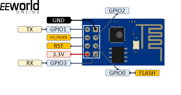
ESP01 ESP8266 Module Pin Diagram
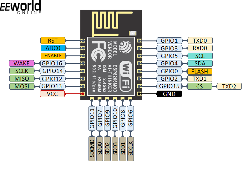
ESP8266-12E bare chip pin diagram
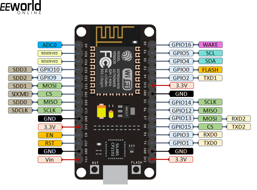
ESP8266-12E NodeMCU Kit Pin Diagram
The ESP8266-12E chip has the following pinout.
The ESP8266-12E breakout board has the following pinout.
Digital input/output in ESP8266
ESP8266 GPIOs are 3V3 compatible and can drain or supply a maximum of 40 mA. As we can see, GPIO6, GPIO7, GPIO8 and GPIO11 are not available for input/output on the ESP-12E breakout board, which is normally available as a NodeMCU kit. GPIO6 is exposed as ADC0 on the breakout board. GPIO6 ~ GPIO11 is connected to the Flash chip. This is why it is not recommended to use them for digital input/output. We are then left with GPIO0~GPIO5 and GPIO12~GPIO16.
GPIO0 is used to configure the ESP8266 in bootloader mode. This is why GPIO0 can only be used after writing MicroPython firmware to the ESP8266. Similarly, GPIO16 is used to wake up the ESP8266 from a deep SL; therefore, it should be avoided for digital input/output if deep sleep mode is used in the embedded application.
When assembling an external circuit with ESP8266, the initialization behavior of its GPIO pins needs to be considered. When the ESP8266 boots up, the board uses GPIO0, GPIO1, GPIO2, GPIO3, GPIO9, GPIO10, GPIO15, and GPIO16. GPIO1, GPIO3, GPIO9, GPIO10, and GPIO16 are pulled HIGH at startup, while other GPIOs except GPIO4 and GPIO5 output a LOW signal. Therefore, if any relay is driven in the circuit connected to ESP8266, only GPIO4 and GPIO5 are suitable for connecting the relays. All other GPIOs may result in unattended relay operations due to strange behavior of the GPIOs with the relay drive circuit during startup. It should also be noted that initialization will fail if GPIO0, GPIO1 and GPIO2 are externally pulled low in the circuit. Initialization will also fail if GPIO15 is externally pulled up into the circuit. Therefore, the following precautions must be taken when assembling an external circuit with ESP8266.
- Any relay driver, if connected to the circuit, must be interfaced to GPIO4 and GPIO5 only.
- GPIO0, GPIO1 and GPIO2 must never be derated by the external circuit.
- GPIO15 must never be raised by the external circuit.
- GPIO16 should not be used for digital I/O if ESP8266 deep sleep mode is used in the embedded application.
- GPIO0 should be avoided if the ESP8266 needs bootloading multiple times during application development.
Finally, it should be remembered that the I2C interface of the ESP8266 is available in GPIO4 (I2C SDA) and GPIO5 (I2C SCL) in the NodeMCU kit. The SPI interface is available in GPIO12 (MISO), GPIO13 (MOSI), GPIO14 (SCK) and GPIO15 (CS). PWM is available on all GPIOs, while interrupts are available on all GPIOs except GPIO16.
ESP32 Features and Pin Configuration
ESP32 is a superior Wi-Fi development board compared to ESP8266. It has 39 GPIOs, of which 34 GPIOs are normal digital inputs/outputs. It comes with 18 ADC channels, 16 PWM output channels, 3 UART, 3 SPI interfaces, 2 I2C interfaces, 2 DAC, 2 I2S interfaces and 10 capacitive sensing GPIOs. The simple ESP-WROOM-32 chip has the following pin diagram.
The ESP32-DevKit V1 has the following pin diagram.
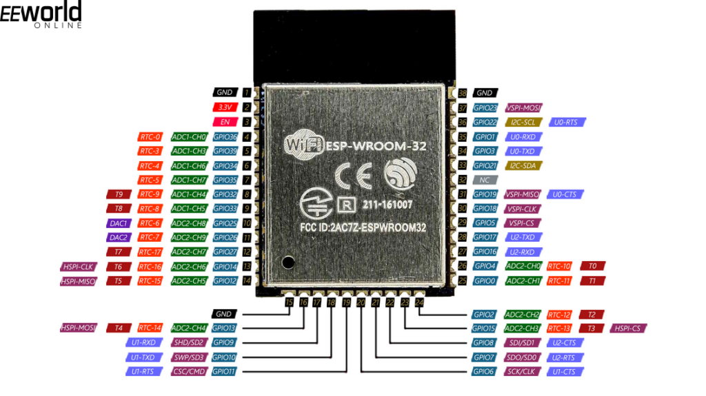
ESP-WROOM-32 chip pin diagram
The ESP32-DevKit V1 has the following pin diagram.
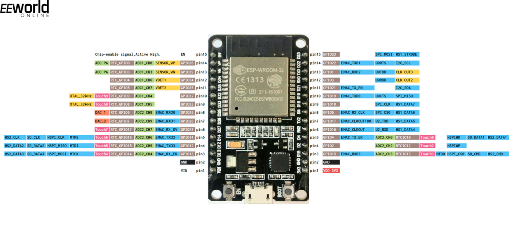
ESP32 DevKit V1 Module Pin Diagram
Digital input/output on ESP32
ESP32 GPIOs are 3V3 compatible and can supply or absorb a maximum of 40 mA. However, the development board can also be powered by a 5V source, as it has an integrated voltage regulator. There are 39 GPIOs in the ESP32. These GPIO6 ~ GPIO11 are connected to the internal SPI flash; therefore, it is best to avoid them. GPIO28 ~ GPIO31 is not exposed on the development board. The GPIO34, GPIO35, GPIO36 and GPIO39 are input only. Rest all GPIOs can be used for both digital input and output.
Just like the ESP8266, the ESP32 also shows some strange behavior in some of its GPIO during startup. GPIO1, GPIO3, GPIO5, GPIO6 ~ GPIO11, GPIO14 and GPIO15 are pulled HIGH during boot, and GPIO0, GPIO5 GPIO14 and GPIO15 output PWM signal during boot. During boot, GPIO1 is enabled to debug output. Therefore, if there is an interface in the circuit, no relay driver should be connected to these pins. Otherwise, the relay drive circuit will exhibit autonomous behavior due to the strange state of these GPIOs during startup.
It should also be remembered that UART is available on the following pins.
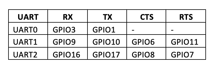
There are two I2C channels in ESP32. The default I2C pins on ESP32 are GPIO21 and GPIO22. However, I2C software can be implemented on any GPIO.
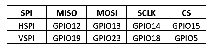
There are 3 SPI channels in ESP32, of which one is reserved for communication with flash memory and two channels are available for use. These two channels are hardware SPI (HSPI) and virtual SPI (VSPI). SPI channels are available on the following pins.
There are 16 PWM channels in ESP32. They can be multiplexed to generate PWM output on all pins except GPIO34 ~ GPIO39. Pin interrupts are available on all GPIOs. The capacitive GPIOs are GPIO4 (T0), GPIO0 (T1), GPIO2 (T2), GPIO15 (T3), GPIO13 (T4), GPIO12 (T5), GPIO14 (T6), GPIO27 (T7), GPIO33 (T8) and GPIO32 (T9). The RTC GPIOs are GPIO36 (RTC_GPIO0), GPIO39 (RTC_GPIO3), GPIO34 (RTC_GPIO4), GPIO35 (RTC_GPIO5), GPIO25 (RTC_GPIO6), GPIO26 (RTC_GPIO7), GPIO33 (RTC_GPIO8), GPIO32 (RTC_GPIO9), GPIO4 (RTC_GPIO10), GPIO0 (RTC_GPIO11), GPIO2 (RTC_GPIO12), GPIO15 (RTC_GPIO13), GPIO13 (RTC_GPIO14), GPIO12 (RTC_GPIO15), GPIO14 (RTC_GPIO16) and GPIO27 (RTC_GPIO17). GPIO38(ADC1_CH2), GPIO39(ADC1_CH3), GPIO32(ADC1_CH4), GPIO33(ADC1_CH5), GPIO34(ADC1_CH6), GPIO35(ADC1_CH7), GPIO4(ADC2_CH0) GPIO13 (ADC2_CH4), GPIO12 (ADC2_CH5), GPIO14 (ADC2_CH6), GPIO27 (ADC2_CH7), GPIO25 (ADC2_CH8) and GPIO26 (ADC2_CH9). DAC channels are available on GPIO25 (DAC1) and GPIO26 (DAC2).
Activating an LED by turning on ESP8266/ESP32
Now equipped with the knowledge of digital input/output in MicroPython and familiar with the pin configuration and features of the ESP8266/ESP32, we can drive components such as LEDs from the ESP8266/ESP32 and control their switching using buttons. Let's turn on/off an LED via a tactile switch in ESP8266 using MicroPython code.
Required components
- ESP8266x1
- LEDx1
- 330Ω x2 resistance
- Push Button x1
- Connecting wires/jumper wires
- Test board
Circuit Connections
Connect the LED's anode to the GPIO5 of the ESP8266 and connect its cathode to ground through a 330 ohm series resistor. Connect the button to the GPIO4 of the ESP8266 pulled down by a 330 ohm resistor.
Note that MicroPython firmware must be loaded into the ESP8266. Python code can be written and sent to ESP8266 using uPyCraft or Thonny IDE.
Python Code
Machine Import Pin
of time matter sleep
led = Pin (5, Pin.OUT)
button = Pin (4, Pin.IN)
while True:
led.value(button.value)
sleep (0.5)
Working
The script starts by importing the Pin class from the machine module and the sleep class from the time module. GPIO5 is configured as a digital output to drive LED. GPIO4 is configured as a digital input with a button connected in a low pull configuration. In the while loop, the output of GPIO5 is set to the input of GPIO4. GPIO4 is dimmed by default, so the LED remains off. Whenever the button is pressed, GPIO4 goes HIGH, a HIGH signal is passed to GPIO5 simultaneously and the LED starts glowing.
Result
(Link to ESP04-DV demonstration video)


