More safety through directional overcurrent relays
Luciano Bertene
This directional overcurrent relay features a unique mechanism that utilizes fault current, armature, solenoid, piston and spring. It is selectively activated when current flows in a specific direction, ensuring precise protection. Unlike traditional relays, it offers manual and automatic reset functions for better control. It plays a crucial role in protecting systems like transformers and preventing damage caused by excessive current. With its power transmission principles, this relay improves the reliability of the entire power distribution system.
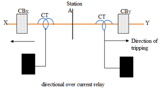
The directional overcurrent relay detects the direction in which the fault occurs relative to the location of the relay. The principle of directional protection is as follows:
Let's consider a feeder line XY that passes through station A. The circuit breaker of the supply line AY is equipped with a directional relay R, which activates the circuit breaker CB. j if the residual current flows only in the AY direction. Therefore, the CBy circuit breaker does not trip unnecessarily in the event of errors on the AX branch. However, if there are defects in branch AY, the CBy circuit breaker trips due to the directional function of the relays that are configured to act in the AY direction. This type of relay is also called reverse power relay in terms of the direction of flow of the fault current (power flow).
Reverse flow relays with directional functions detect flow direction and measure the intensity of power flow.
Directional relay connections
When a compare or close fault occurs, the voltage becomes low and the directional relay may not be able to develop sufficient torque for its operation. To obtain sufficient torque for all types of faults, the relay connections must be changed independently of the relay positions. Each relay is energized by the current of its respective phase and voltage. One of the methods for such connections is a 30 Ó connection, and the other is a 90 Ó connection.
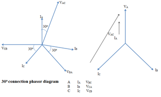
30 Ó Vector connection diagram
In this type of 30 Ó With this connection, the relay current coil of phase A is energized by the current pointer I. A and the mains voltage V air conditioning —also the relay in phase B to I b and V BA and phase C to I C and V CB . The relay develops maximum torque when current and voltage are in phase.
90 Ó Connection vector diagram
In the above 90 Ó Connection, the relay in phase A is energized by I A and V before Christ Phase B to IB and VCA and Phase C to I C and V ABSENT . The relay is designed to develop maximum torque when the relay current leads the voltage by 45. O .
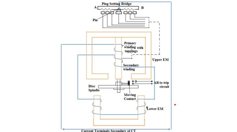
Construction details and functionality of a non-directional overcurrent relay
It has a metallic disc rotating freely between the poles of two Electromagnets (EM).
The spindle of this disc carries a movable contact that connects two fixed connections when the disc rotates at an angle between 0 Ó and 360 Ó . By adjusting this angle, the path of the moving contact can be adjusted so that the relay can obtain any desired time setting, indicated by a pointer; the dial is calibrated from 0-1. The nameplate curve relay time must be multiplied by the time multiplier setting.
The top magnet has two windings. The primary coil is connected to the secondary current transformer through taps. These faucets are with the Plug Adjustment Bridge . The secondary part is connected to the lower electromagnet; the torque exerted on the disc arises from the interaction of eddy currents generated by the flow of the upper EM and the lower EM. The relay setting is 50% to 200% in 25% increments.
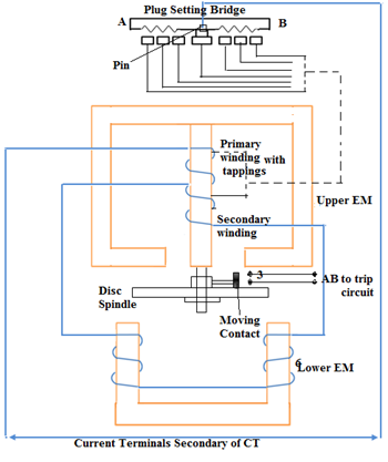
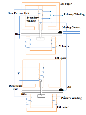
Construction and working details of directional overcurrent relay
A directional overcurrent relay activates when current exceeds a certain value in a fixed direction. It contains two relay units, an overcurrent unit and a directional unit. For the directional unit, the secondary winding of the overcurrent unit (relay) is kept open (AB). When the directional unit is actuated, it closes the available contacts of the secondary winding of the Wattmeter or shaded post type relay.
Under normal operating conditions, the current in the circuit flows in the normal direction and is protected by the relay. Therefore the steering unit does not work. When a short circuit occurs, current or power tends to flow in the opposite direction. In this case, the directional unit disk rotates to join the fixed contacts A and B and complete the overcurrent team circuit. Consequently, the disk of the overcurrent unit rotates and the moving contacts attached to it close the trip circuit. This activates the circuit breaker, isolating the faulty section.
The directional drive is very sensitive so that at the lowest voltage value expected under severe fault conditions, the current will produce sufficient torque to complete the operation and allow the contacts to close.
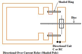
Directional overcurrent relay with shaded pole design
A directional relay responds to fault currents flowing in a specific direction. The directional function is achieved by installing a directional unit as shown in the figure.
The main flow is divided into two temporally and spatially displaced shifts with the help of a shaded ring . The air gap flux of the shaded pole lags behind that of the unshaded pole. The illustration shows how an Induction Disc Overcurrent Relay with Separator, That is, a shaded pole magnet that also has a directional unit consisting of a capacitance C or a resistance-capacitance circuit RC works as a directional relay.
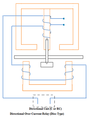
The image above shows the wattmeter type induction relay . Here, a steering unit controls the angle between the two flows by varying the RX parameters of the lower electromagnet. Another control method in the wattmeter type is to power the lower winding from a separate voltage source. If the voltage from this source is equal and opposite to the power of the upper magnet's secondary winding, no current flows in the lower coil. Therefore, no torque is generated. If it is opposite and less than secondary production or if it supports secondary production, there is an Operating Torque . When the source voltage deviates and exceeds the secondary output voltage, the lower coil current is reversed, producing torque. This last method is used in Translation Relay .
Na era digital em constante evolução, a escolha da linguagem de programação certa pode fazer toda a diferença no desenvolvimento de aplicativos desktop. Duas opções que têm se destacado nesse cenár...
O aço damasco é um material fascinante que tem cativado a imaginação de artesãos, engenheiros e entusiastas por séculos. Sua história remonta à antiga Índia e ao Oriente Médio, onde foi comercializ...
O aço patinável, também conhecido como aço corten, é um material cada vez mais utilizado na fabricação de equipamentos de transporte, como vagões ferroviários, contêineres e outros. Isso se deve às...
O setor automotivo brasileiro tem vivido um momento de recuperação e crescimento nos últimos meses. De acordo com os dados mais recentes, as vendas de veículos no país registraram um aumento de 8% ...
A solda MIG (Metal Inert Gas) é uma técnica amplamente utilizada na indústria e construção devido à sua eficiência, versatilidade e qualidade dos resultados. No entanto, um componente crucial neste...
A soldagem por arco submerso (SAW) é uma técnica amplamente utilizada na indústria, conhecida por sua alta taxa de deposição e capacidade de soldar chapas grossas e estruturas pesadas. Este process...
A construção civil está passando por uma transformação revolucionária com a adoção da tecnologia de impressão 3D. Essa inovadora abordagem está redefinindo a maneira como construímos casas e edifíc...
Cálculo de Carga de Compressão em Barras de Aço
A análise da segurança de estruturas compõe um dos conceitos mais importantes na ingenieria civil. Nesta área, a compreensão da carga de compressão ...