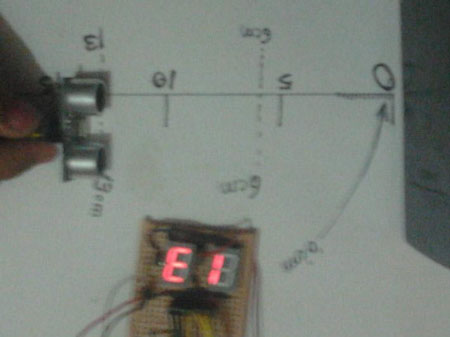
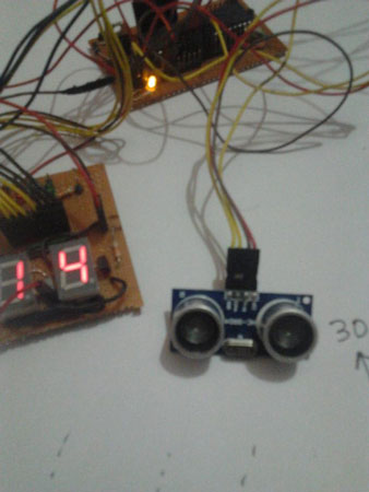
Distance finder based on HC-SR04 gives the distance to an obstacle in centimeters. It has a range of 2 cm to 400 cm. The project is built around the AT89S52, which is a microcontroller from the 8051 family. Distance is displayed on seven-segment displays.
Components:
AT89S52
Three 7 seconds. Expense (Common anode type)
HC-SR04 (ultrasonic sensor module)
Connectors, PCBs etc.
The code is written in Assembly and is easily understandable. The project can be used in robots to avoid obstacles, etc.
Working:
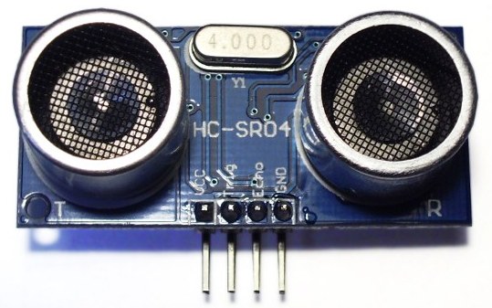
The operation of ultrasonic sensors is quite simple and easy to interface with the microcontroller. The sensor module has 4 pins, of which Pin-1 and Pin-4 are +Vcc and Gnd respectively. Pin-2 is Trigger and Pin-3 is Echo pin.

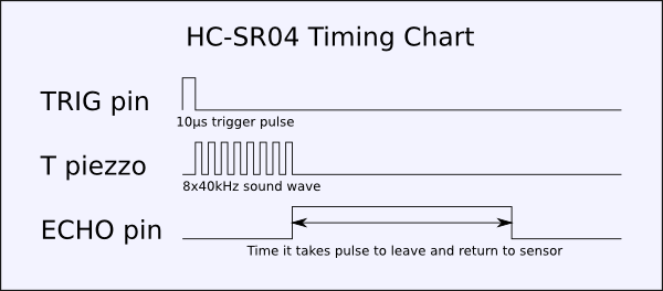
When a high pulse of 10us is applied to the TRIG pin, the ultrasonic transmitter sends 8 consecutive pulses of 40kHz frequency. As the eighth pulse is sent, the sensor's ECHO pin becomes HIGH. Now when ultrasonic waves are reflected from any surface and are received by the receiver, the ECHO pin goes LOW. The time it takes to leave and return to the sensor is used to find the distance to the reflecting surface.
Distance in centimeters = (Time/58) cms
In inches = (time/148)
The distance can also be calculated taking into account the speed of sound (=340m/s)
CODE Explanation:
· The data lines of seven-segment displays are interfaced to port-0
· Port-1, Pin-0,1 and 2 are selected lines for SSDs
· P3.0 is connected to Trig
· P3.1 is connected to the Echo pin of the sensor module
· In the main part of the Program, first Timer-1 is initialized in mode 2 (8-bit auto-reload)
When P3.0 is set high, the DELAY1 subroutine is called. After 10us P3.0 is reset to 0
· Now P3.1 is checked for a high signal. As P3.1 gets high, Timer 1 starts and every time it overflows, Register A is incremented.
· The loaded count value should be 58 (mentioned in the datasheet). So that after 58 cycles A is incremented once. But since the delay caused by instructions needs to be compensated, the count value I used was 45 (=> 255D-210D).
· The value stored in A is used to extract the measured Distance. This is done by Division instruction.
· The 8-bit data value is sent sequentially to the respective 7-segment display and is selected through the selection lines.
Project source code
 ###

 ORG 00H
| 3 | 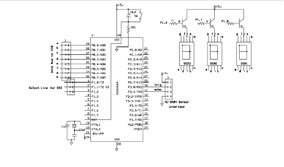 |
Project video
 Ask and discuss on the EDAboard.com and Electro-Tech-Online.com forums.
Tell us what you think!! Cancel reply
You need to be logged in to post a comment.


Questions related to this article?