In this tutorial I will teach you how to make the graphical interface of the 128×64 LCD with the 8051 microcontroller (89c51,89c52). 128×64 means lcd has 128 coulombs and 64 lines. Which means you can make your desired image or text in a 128×64 square matrix. Graphic LCDs come in various sizes, but they also differ in features. Some can be connected directly to your PC and you just need to learn simple commands to send images and text to the LCD, these graphical LCDs come with free software. Some are just simple LCDs and you need to control them with some smart unit like microcontroller etc. In this tutorial we will control the same simple graphical LCD using 89c51 microcontroller. We will display text on graphical LCD using 8051 microcontroller.
How do graphic LCDs work?
I am going to interface the jhd12864e graphic lcd with 8051 microcontroller. To know more about the complete pin description and internal pixel organization of the jhd12864e graphic lcd, please follow the simple tutorial. This will lead you to easily understand the code written below.
- 128×62 Graphic LCD Pinout and Description
The above tutorial is very important to understand the GLCD code below. If you don't know about the working of GLCD then you can't understand 8051 microcontroller with below GLCD code. The pinout of GLCD jhd12864e is given below.
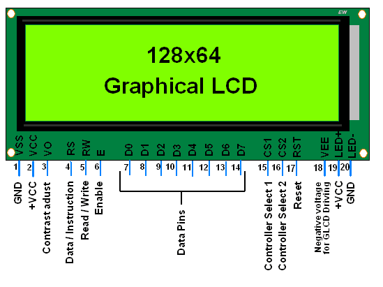
JHD128x64 LCD graphic pinout
JHD12864e GLCD with 8051 microcontroller
I will print my website name “ microcontroller-project.com ” in glcd. First I decided on the text font to display in GLCD. II finalized the character height to 8 lines and 5 to 6 coulombs wide. You can display the text according to your desire. Since you have a lot of space available from 128 coulombs to 64 lines. Combine the pages to make the font bigger and bigger (if you don't know what a page is on the graphic LCD, follow the tutorial above).
Steps to display text in GLCD
- Initialize glcd jhd12864e (display on-off, set x, y address, set start line)
- Select the graphical half of the LCD (left or right) I don't understand! Take the top tutorial.
- Select the I don't understand! Take the top tutorial.
- Make and display text I don't understand! Take the top tutorial.
How is text created and displayed in GLCD?
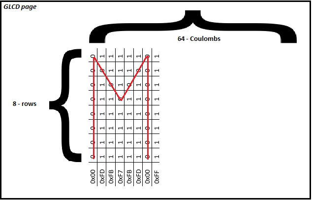
Now when you are done initialize glcd and select glcd half and page. It's time to create/display text or image in glcd. Each GLCD page is organized into lines and coulombs (8×64 in dimension) 8 lines and 64 coulombs. Each coulomb on a page has 8 vertically aligned points. We send eight-bit data to turn these points on or off. 0 is OFF and 1 is ON. A simple command like FF = 11111111 turns on all Coulomb points and F0 = 11110000 turns off the first four points and turns on the last four. You create the text or image you want by turning these pixels on or off. The combination of all coulombs forms an image.
For example, to display the ' M ' in Glcd, the data sent to GLCD is below. Data is sent to the glcd 8 bits at a time. 8-bit data is in hexadecimal format. If we translate hexadecimal to binary, it will represent the character below. The last command is not displaying anything. It is actually the gap for another character to appear as an ' M ' head.
Creating and displaying characters on the GLCD page
JHD12864e interface with 8051 microcontroller – Project circuit diagram
The circuit diagram of the project is simple. Connect port 1 of the 8051 microcontroller (89c51,89c52) to the data pins of the graphical LCD. Pin 0 of port 3 is connected to the rs (register select) pin of the graphical LCD. Pin 1 of port 3 is connected to rw (graphic LCD read and write pin). Pin 2 of port 3 is connected to the EN (enable) pin of the LCD. Pins 3 and 4 of port 3 are connected to CS1 (Chip Select 1) and CS2 (Chip Select 2) on the 128×64 graphic LCD. Pin 5 of port 3 is connected to the reset pin of the 128×64 graphical LCD. The rest of the connections are for initializing the 8051 microcontroller. The circuit diagram of the project is below.
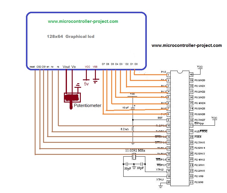
Graphic LCD with circuit diagram 8051 (89c51,89c52)
GLCD interface with microcontroller code 89c51
Coming to the GLCD project code. It is written in C language using Keil Uvision 3 software to compile and create hexadecimal code. First the reg51.h header file is included (must be included in all projects made in keil for 8051 microcontroller). Then, Port-3 single bits are set. These pins are used to control the JHD12864E graphic LCD. delay function is generating some delay for us to be used when needed. lcdcmd function is sending commands to glcd. lcd data function is sending data to glcd. The main function is to control all display and control functions. Each command is praised for its function.
While(1) loop at the end executes the code only once. Website name “ microcontroller-project.com ” will be displayed on two pages of jhd12864e.
Note: Some graphic lcds select cs1, cs2 (chip select) at 1 and some with 0. If you are using this code, make sure 0 selects your cs1 and cs2. If it is not 0, switch cs1 and cs2 in the code, just do cs1 = 1 where it is 0 and cs2 = 0 where it is 1.
Some more microcontroller projects involving jhd12864e graphic lcd are below. Images are also displayed on GLCD using various microcontrollers.
- JHD12864E Graphic LCD with Pic Microcontroller
- Displaying images on 128×64 graphical LCD
Download the project files. The folder includes project code (Hex,c++) and simulation. The code is written in ce language keil uvision 3 is used to compile the code. The simulation is done in Proteus 8. If you have any questions, write below.
Graphic LCD with 8051 files/code


