This tutorial will teach you how to use and program the HMI (Human Machine Interface) display. HMI displays have been on the market for a long time, but their price has dropped in the last couple of years, and now DIY manufacturers are using them in projects.
Please note that the HMI screen is different from the touch screen. The touch screen only displays the text or image that the user submits for display. However, the HMI is not just a touch screen. It can also process data by itself and take further action based on the programmer's programmed software.
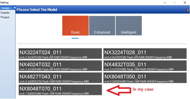
Nextion HMI displays are the most popular among DIY enthusiasts and we will learn how to program, interface and work with them. Download and install nextion GUI builder editor. Once installed, open the editor and start creating a new project. Go to File>New in the window and give the project a valid name and the project will be saved with. HMI Extension. After creating the project, a new window will appear where you will be asked to select your HMI. Nextion offers several HMIs in Basic, Enhanced, and Smart categories. Find your HMI category, name it, and select it.

NX8048T070_011 is 7 inches 800×480. When finished, click OK . Next, the screen orientation must be selected. Select the display orientation. You can also select the character encoding. I prefer to work with the iso-8891-1 standard. Hit OK, and you are done with the display settings.

Main editor window
The main editor window comprises many small windows, each used to define different parameters/functions and settings, overlooking the main window and its subwindows.

Let's create two pages and jump from one to the other. In the main page header, I want to display the EngineersGarage logo. So first I need to import the logo into the editor. Click the add button, navigate to the image and press Enter. The logo is imported and displayed in the window. The logo parameters size, height, width and format appear below it. The logo is assigned an ID-0. Each object in the editor is assigned an ID.
 To place this image in the display pane, double-click the image object. A rectangular box will appear in the display pane. p0(picture0) is the name of the object.
 To display the EngineersGarage logo in the image box, click the box and navigate to the attributes window. The P0 attributes are listed in the window. Id is 1, scope is local (if it is global then this object can be seen on other pages). The photo attribute is where we have to place the id of the image we want to display in the image box. In our case, the logo ID is 0, so put 0 and press Enter (you can also use the browse feature to manually select the available images in the image window). The logo will appear in the image box.
 Make sure your image is not outside the display panel. Adjust it in a panel using the mouse.

Display text
To display the text first, we have to generate a font. The font generator application is part of the editor. Navigate to Tools > Font Generator .

Generate the font you want to display on the HMI. Give each font a valid name, select height and encoding, etc. If more than one source is part of the project, generate each one one by one.
 I specified two sources. You can preview fonts in the fonts window. Each source is given an ID and a name.
 To assign a text box to a specific font, insert the font ID next to the Font attribute. TXT attribute is where you enter the text, which later appears in the text box. Pco attribute changes the color of the text. Each object and its attributes can be studied using the editor's help option.
 I created two pages with few images and text boxes present on each page. A button is placed on the main page. Pressing the button will take you to the next page.
 To switch between pages using a button, we must create an event. The event can occur when pressing or releasing the button. I specified it at launch. Place page Page 1 in the button release event. Commands can be studied using the help of the editor menu.
 Now all you need to do is compile the code and start debugging.
Note: You don't need any external hardware for this project – just a power supply to power the HMI.
Loading the sketch to HMI
After successfully debugging the GUI application, it is time to load the sketch into the HMI. The best solution is to charge it using a USB to TTL converter. Connect the serial converter to the USB port and its UART lines with HMI. In the text editor on the toolbar, select the COM port, set the baud rate to 9600 and click upload. The sketch will begin uploading and will take 3 to 6 minutes depending on the size of the application.
Another method is to copy the .TFT file generated by the nextion editor to an SD card. Insert the card into the HMI's SD card slot and turn on the HMI. The GUI program will be automatically loaded into the HMI. You can remove the SD card when the upload is complete.
Let's do it yourself: where to buy parts?
Mouser: Nextion HMI Screen
Mouser: USB to UART
Mouser: Power supply


