Interrupts with NRF24LE1
In our daily lives we are often distracted or interrupted by other people. In this condition we suspend our ongoing work and pay attention to what others have to say. We only resume our previously suspended work after the interrupted task has been completed. The master that controls the processing of thoughts in us is our brain. The brain stops processing ongoing thoughts when we are interrupted and starts processing the other task. It resumes previous processing in progress when the task is complete. The controller works in a similar way. Here we will study the interruptions associated with our NRF.

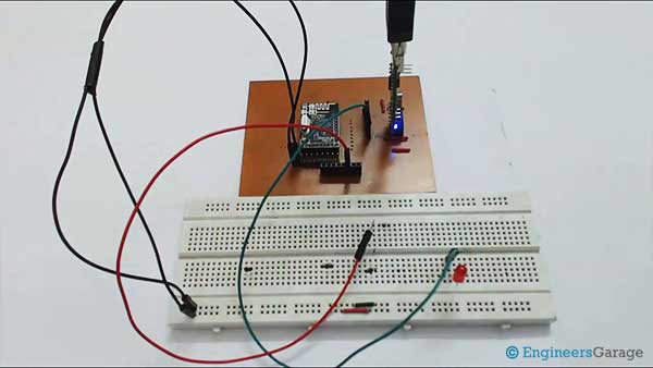
Fig. 1: NRF24LE1 Interrupt Demonstration Prototype
We all know the task of interrupts in any controller. It tells the microcontroller to suspend the current code execution, save the current state, and process the interrupt request. The controller processes the interrupt request by jumping to the Interrupt Service Routine (ISR) or the Interrupt Handler. ISR is a function or procedure defined in the code that is executed when an interrupt occurs. The same happens with the NRF.
In the NRF24LE1, there are a total of 18 interrupt sources, of which 4 are hardware-based and the rest are software-based. Each interrupt source has a vector address to which the ISR must be written. These interrupts can be level-triggered (low/high) or edge-triggered (rise/fall).
The attached image consists of different fonts, vector address, polarity and its description.
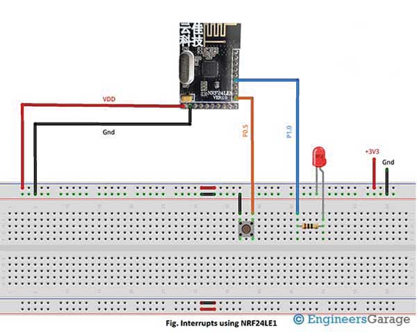
In the 32-pin package, there are 2 external hardware interrupts: INT0 and INT1. The interrupt pin for INT0 is P0.5 and for INT1 it is P0.6.
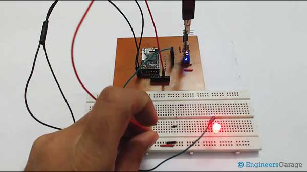
Figure 2: NRF24LE1 Interrupt Demo Image
Interruptions can be controlled through various logs detailed below:
• Interrupt Enable 0 Register (IEN0) – An 8-bit register used to enable/disable global interrupts and individual interrupts for Timer0, Timer1, Timer2, Port 0, and Serial Port.
• Interrupt Enable Register 1 (IEN1) – An 8-bit register used to enable/disable RF, SPI, and Timer2 interrupts.
• INTEXP – This register enables/disables 2-wire SPI interrupts, master and slave. This register is also used to choose between INT0, INT1 and INT2.
• IP0 and IP1 (Interrupt Priority) – Two 8-bit registers used to set priority levels between different sources.
• Interrupt Request Control Register (IRCON) – An 8-bit register that contains interrupt request flags.
For software interrupts, we need to enable them according to the features we are using. For example, if we are using Timers then we will enable the Timer interrupt which is associated with the internal timers of our module.
We are currently focused on discussing INT0 hardware interrupts. Some simple steps through which we can configure INT0 are:
• First write 1 in bit7 of IEN0 to enable global interrupts and 1 in bit0.
• Write 1 in bit3 of INTEXP to select INT0.
We also wrote code to explain how the INT0 interrupt works. Additionally, an LED blinking program has been written into our interrupt service routine. Therefore, the LED will flash whenever an interruption occurs.
Check the commented code for more details. Stay tuned for more articles in the series.
#include"hal_delay.h" // header file containing delay functions
#include"isrdef24le1.h" //header file containing interrupt service routine definition for NRF24LE1
// Main code
main void
{
P0DIR = 0xf0; //take the upper 4 bits of Port0 as input
P1DIR = 0; // define port1 as output
P1=0x00; // makes all Port1 pins low
IEN0 = 0x81; // enable pin interrupt
INTEXP = 0x08; // enable INT0
while(1); //infinite loop, wait for interrupt
}
// Interrupt service routine
EXT_INT0_ISR
{
P1 = 0xff; //makes all Port1 pins high
delay_ms(1000); // 1 second delay
P1=0x00; //makes all Port1 pins low
delay_ms(1000); // 1 second delay
}


