Switch interface with black Beaglebone
This tutorial explains how to interface the Switch with the Beaglebone black, where the Switch acts as an input device. It's a simple learning tutorial on using GPIO pin as input. The program is written in python script with adafruit GPIO library. It's not a big deal, but you need to get the fundamentals straight before developing a high-end application.
Required tools :
- Black Beaglebone
- Led
- push button
- 330Ω resistor
- 1 kΩ resistor
- Test board
- Female to female connectors
Software environment configuration
Install the latest version of python on BBB as explained in the tutorial How to make the first python program with Beaglebone Black. Install the adafruit python-GPIO library called adafruit_BBIO.
Working
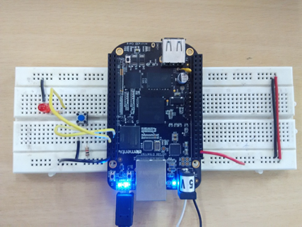
It is a simple black Beaglebone learning tutorial. Here I connected the LED and switch with the GPIO pin on the black Beaglebone. When the script is running, it enters the end of the continuous loop. When the switch is pressed, the LED is on, otherwise it is off. Press Ctrl+C to stop program execution in the SSH command terminal.
Description
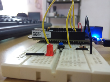
Let's first prepare the circuit connection. Take a breadboard and supply VCC and ground from BBB to the breadboard line. Connect 3.3V power from pin number 3 third of header P9 and ground from pin number 2 and header P8. Connect the negative terminal of the LED to ground. Connect the 330 ohm resistor to the positive terminal of the LED. Connect other end of the 330 ohm resistor to pin number 8 of connector P8. The push button has two terminals. Any of them connect to the ground. Supply 3.3V to 1k ohm VCC resistor to other button terminal. Common end of resistor and button, connect with pin number 9 of header P8. Supply power to the black Beaglebone by connecting to the PC via a USB cable. Now your circuit is prepared.
Open the command terminal and access Beaglebone black through SSH as explained in getting started with Beaglebone black. Create a new file using play command with .py extension (i.e. led.py). Open the file with any text editor (i.e. nano, vim etc.) and write code in python language.
GPIO pin configuration
Import the GPIO library from the adafruit Beaglebone black library by calling the following line in the program:
import Adafruit_BBIO.GPIO as GPIO
You can set the pin number to a pin number with underscore followed by the pin number. (i.e. P8_8). Give the PIN number an appropriate name.
i.e. BUTTON = “P8_9”
Here I have assigned the name BUTTON to pin number 9 ah header P8.
Next, configure the pin as input or output according to the following function:
GPIO.setup (pin number, output/input)
For example, I declared the button (pin number 9 oh header P8) as input by the following line:
GPIO.setup (BUTTON,GPIO.IN)
Note: here I declared switch as input. (led is input device)
You can read the input pin status by following the function:
GPIO.input (pin number)
For example,
GPIO.input (BUTTON)
You can make the pin high and low by following the function:
GPIO.out ( High or low PIN number )
For example, I make LED (pin number 9 oh P8 header) as High and Low following the line:
HIGH: GPIO.output (LED, GPIO.HIGH)
LOW: GPIO.output (LED, GPIO.LOW)
Run the script in the terminal:
Enter the following command with the file name at the command prompt:
python.py file name
i.e. python switch.py