This tutorial explains how to interface the DC motor with the black Beaglebone, where the DC motor acts as an actuator device. Due to insufficient current, it is not possible to drive the motor directly from BBB and hence a motor driver IC is required. The program is written in python script with the Adafruit GPIO library.
Required tools :
- Black Beaglebone
- DC motor
- Driver IC (i.e. L293D)
- push button
- 1 kΩ resistor
- 0.1uF Capacitor
- Test board
- Female to female connectors
Software environment configuration
Install the latest version of python on BBB as explained in the tutorial How to make the first python program with Beaglebone Black. Install the Adafruit python-GPIO library called adafruit_BBIO.
Working
I interfaced the DC motor and switch with the Beaglebone Black's GPIO pin. When the script runs, it enters a continuous loop. One press of the switch will start turning the motor clockwise, while another press will turn it off. Press Ctrl+C to stop program execution in the SSH command terminal.
Description
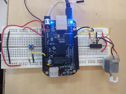
Let's first prepare the circuit connection. Take a breadboard and supply VCC and ground from BBB to the breadboard line. L293D operates at least 4.5V while Switch and GPIO operate at 3.3V. BBB has 5V system-on-chip and 3.3V pin header. So you can take both supplies from Beaglebone Black. System 5V is consumed for L293D and 3.3V is consumed for switch and GPIO.
On one side of the breadboard, connect 3.3V power from pin number 3 third of header P9 and ground from pin number 2 and header P8. On the other hand, connect the 5V power system to pin number 8 of header P9 and make common ground with pin number 2 of header P8.
The push button has two terminals. Any of them connect to the ground. Supply 3.3V to 1k ohm VCC resistor to other button terminal. Common end of resistor and button, connect with pin number 30 of header P9.
L293D is a motor driver IC that allows you to drive the motor in both directions. The DC motor drive has high current capacity, but the BBB GPIO pin cannot generate enough current to drive the DC motor. L293D IC overcomes this problem and is required to interface between BBB and DC motor. The L293D also protects the BBB from damage due to the back emf generated by the DC motor.
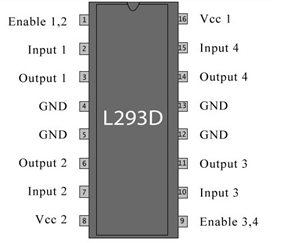
The BBB output is connected to the L293D input. Pin number 8th and 9th of header P8 act as positive and negative terminals of the motor respectively. Take the input of these pins and connect with input1 ( 2nd pin of L293D) and input2 ( 7th pin of L293D) Pin of L293D respectively. Interface the DC motor between output 1 ( 3rd pin of L293D) and output2 ( 6th pin of L293D) pin of L293D. Supply 5 V from the system to both the VCC ( 16th pin of the L293D) and VSS ( 8th pin of the L293D) pin of the L293D. VCC is the source for internal logic translation in L293D and VSS is the power supply for the 5V driver.
I connected a 0.1 uF capacitor between the output 1 and output 2 terminals for alignment and back emf protection. Supply power to the black Beaglebone by connecting to the PC via a USB cable. Now your circuit is prepared.
Open the command terminal and access Beaglebone black through SSH as explained in the tutorial starting with Beaglebone black. Create a new file using play command with .py extension (i.e. led.py). Open the file with any text editor (i.e. nano, vim etc.) and write code in python language.
GPIO pin configuration
Import the GPIO library from the adafruit Beaglebone black library by calling the following line in the program:
import Adafruit_BBIO.GPIO as GPIO
GPIO configuration and function I have already explained in the tutorial LED interface with Beaglebone Black and switch interfaced with Beaglebone black .
Run the script in the terminal:
Enter the following command with the file name at the command prompt:
python.py file name
i.e. python dcMotor.py