This is a simple tutorial on how to interface seven segment display with 8051(89c51,89c52) microcontroller. The post/tutorial explains the connections and interface of the 7-segment display with the 89c51 microcontroller. The 7-segment display is interfaced with port 1 of the 89c51 microcontroller. Numeric characters from 1 to 9 and alphabets from A to F will be displayed on a unique seven-segment display using the 89c51 microcontroller.
7-segment display types
There are basically two types of seven-segment displays: anode and cathode. First I would like you to do a simple tutorial on what is the difference between the two
- Difference between common anode and cathode seven-segment displays.
The above tutorial will help you determine which seven segments you are using anode or cathode. You will become familiar with the pinout and internal structure of the seven-segment display. The top tutorial will also explain what are the pros and cons of using anode and cathode seven-segment monitors.
7-segment display with 8051 microcontroller – circuit diagram
The project circuit is simple. No confusing circuit connections. I am using a seven-segment common anode display in the project. 7-segment common anode display LEDs are turned on when we do any LED pin grounding. The 11.0592 MHz crystal is used to supply clock to the 89c51 microcontroller. The circuit diagram of 8051 microcontroller with 7-segment interface is given below.
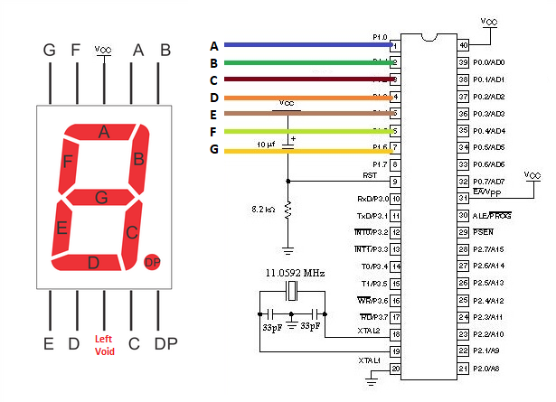
7-segment display with 8051 microcontroller
The 7-segment display above interfaced with the 89c51 microcontroller translates into something given below. I just removed the wires in the diagram above. Wires make the circuit confusing. Both circuits are the same. No difference in connections or operation.
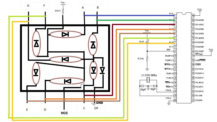
seven segment display interface circuit diagram of 8051 microcontroller (89c51)
8051 Microcontroller Port 1 with 7-segment Interface – Individual Pin Connections
The connection of 7 segment pins with the individual pins of port 1 of the 89c51 microcontroller is shown in the image below. The 7-segment display has only 7 pins out of seven, and port 1 of the 8051 microcontroller is 8 bits wide. Therefore, one pin of port 89c51-1 is empty.
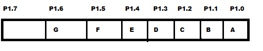
8051(89c51,89c52) Port 1 pin assignment for seven-segment display
How are numbers and characters displayed on the 7-segment display?
The port pins of the 89c51 microcontroller are assigned to seven segments in the above order (image). Instructions like P1=0xCF are hexadecimal instructions and make port 1 pins high or low.
As P1=0xCF is equivalent to 11001111(C=1100 and F=1111) in binary. This instruction makes (P1.5 and P1.4) seven-segment ground pins and the LEDs corresponding to these pins go high. which prints 1 on the seven-segment display.
Below are the complete instructions used to display numbers and letters on the 7-segment display. These instructions are encoded in the code.
- Doing 1-fe is grounded P1=0xCF; 11001111
- Doing 2-abged is grounded P1=0xA4; 10100100
- Doing 3-abcdg is grounded P1=0xB0; 10110000
- Doing 4- bcfg is grounded P1=0x99; 10011001
- Doing 5-acdfg is grounded P1=0x92; 10010010
- Doing 6- acdefg is grounded P1=0x82; 10000010
- Doing 7- abc is grounded P1=0xF8; 11111000
- Doing 8-abcdefg is grounded P1=0x00; 00000000
- Doing 9-abcfg is based P1=0x98; 10011000
- Doing A-abcefg is based P1=0x88; 10001000
- Making B-abcdefg is based P1=0x00; 00000000
- Doing C-adef is based P1=0xC6; 11000110
- Doing D-abcdef is based P1=0xC0; 11,000,000
- Doing E-adefg is based P1=0x86; 10000110
-
Do F-aefg is grounded P1=0x8E; 10001110
7 segments with 89c51 microcontroller – Code
Coming to the code first, I have included the required header file reg51.h. If you are using keil to write and compile code, you must include this library, otherwise an error will occur while compiling the code. If you are using 89c52 or 89s52, include the reg52.h library instead of reg51.h. Then a delay function is used to give some delay to a specific character/alphabet or number to remain printed on the seven-segment display. The delay is to view the character/alphabet or number for a while and then move on to the next one. If there is no delay, the numbers will be displayed so quickly that we will not be able to see them. In the main function my first instruction is P1=0x00. This instruction initializes Port-1 as the output port. The rest of the instructions are in hexadecimal format and their functions are discussed above.
Note: If you are using the common cathode seven segment display, the upper commands will be the same, just make a small change, turn 0 (zeros) to 1 (ones) and 1 (ones) to 0 (zeros) because the Common cathode lights its LEDs when any pin is high.
The while loop 1 continuously runs our seven-segment display. It means continuously printing characters and numbers on it.
More microcontroller projects involving 7-segment display. Each microcontroller project contains free source code and circuit diagram of the project. The seven-segment display is used for different purposes in each project. The list of 7-segment microcontroller projects is below.
7-segment display with Arduino Uno interface
7-segment display interfaced with stm32 microcontroller
WiFi controlled 7-segment display using Nodemcu
Download the project files. The folder contains code (c++, hex). Give your feedback on the post. If you have any questions, leave them below in the comments section.
segment 8051-seven project


