
Figure 1: RS232 Connector
Serial interfacing is one of the most common protocols for making two electronic devices communicate. In such interfaces, data is sent sequentially and bit by bit. RS232 is a subtype of serial interface that was introduced in the year 1932. Available in 9-pin and 25-pin configurations, RS 232 pins allow data exchanges at a maximum of 256 kbps.
Some well-known applications of these connectors include connecting modems to computers and other microcontroller-based UART electronic devices. Of course, such an interface would require different types of connectors; In this case, RS232 connectors are used. The Insight covers a conventional 9-pin female RS232 connector. Let's find out the external and internal details of this.

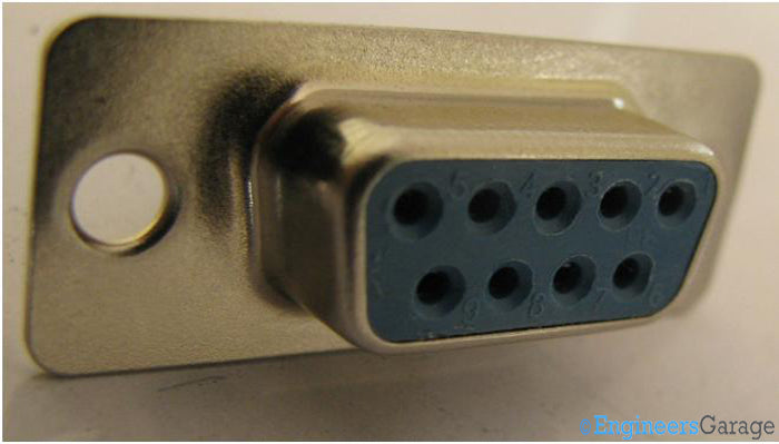
Fig. 2: Image of the 9-pin female RS 232 connector
Input pins : Image 02 shows a 9 pin RS 232 connector . The pin entries are engraved into a plastic frame encased in a metal casing. The pins are numbered by the manufacturer (as seen in the image). Its functions are mentioned below:
Pin 1: Data carrier detection
Pin 2: Received Data
Pin 3: Transmitted Data
Pin4: Data terminal ready
Pin5: Signal ground
Pin6: Dataset ready
Pin7: Send Request
Pin8: Clear to send
Pin9: Ring indicator
The metal box has circular sections cut into its end to facilitate assembly.
Output pins and frames
Output pins

Fig. 3: Output pins
Output Pins : Corresponding to the front, 9 output pins are located on the reverse side of the connector. Just like the input pins, the output pins are also numbered.
Plastic Frames

Fig. 4: Disassembled casing and plastic structure that houses the connector pins
Plastic Frames : The box is divided in two to reveal the plastic structure that houses the pins.
Pin positioning and structure
Pin positioning and structure

Fig. 5: Two pieces of plastic molding that hold the pins
Pin Placement : The plastic frames are opened further to get a better view of the pins. The image above shows the two parts that hold the pins.

Fig. 6: Image indicating the shape of the pins
Pin Structure : A “Y” shaped pin is knocked out of the plastic frames. The cut sections made in the plastic frames are seen to have different openings for different ends of the plastic pins.
Fig. 7: “Y” shaped pin
The pins are in a “Y” shaped structure. The part that is soldered has a curved end to facilitate strong soldering connections, while the part that receives the input pin has two nearby arms that help in properly fixing the device.