Hysteresis, eddy currents and copper losses in transformers
Luciano Bertene
Transformers are important devices in electrical engineering because they allow the efficient transfer of energy between different voltage levels. However, like any electrical component, they are not immune to losses that can affect their performance. Three main losses in transformers are hysteresis, eddy currents and copper losses. These losses contribute to transformer inefficiency, leading to a deeper understanding of their causes and effects. In this discussion, we take an in-depth look at the concepts of hysteresis, eddy currents, and copper losses, examining how they affect the operation of transformers and what strategies are used to mitigate them.
Magnetic flux and permeability in transformers
The ability of iron or steel to retain magnetic flux is much greater than that of air, and this ability to allow magnetic flux to flow is called porosity. Most transformer winding cores are made from low-carbon steels that can have a permeability of 1,500, compared to just 1.0 for air.
This means that a laminated steel core transmits a magnetic flux 1,500 times stronger than air. However, once a magnetic flux flows in the steel core of a transformer, two types of losses occur in the steel. One of them is called “eddy current losses” and the other is called “hysteresis losses”.
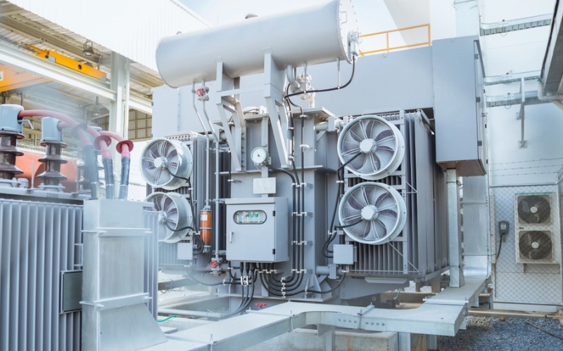
Transformer Cooling Methods
Transformer cooling methods play a crucial role in maintaining the optimum operating temperature of electrical transformers and ensuring their efficient and reliable performance. Transformers are important components of power systems and are responsible for voltage regulation and distribution. However, transformers generate significant heat during operation, which if not managed effectively can lead to numerous operational problems and even catastrophic failures. Various cooling methods have been developed to mitigate these risks, dissipate heat from transformers and maintain their temperature within acceptable limits. These methods include traditional techniques such as air and oil as well as innovative approaches such as liquid cooling and forced air cooling. By using these cooling methods, engineers can extend the life of transformers, improve energy efficiency and ensure the smooth functioning of critical energy infrastructure.
Hysteresis losses
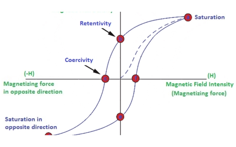
Hysteresis losses arise from the friction of molecules against the flow of magnetic lines of force necessary to magnetize the nucleus, whose value and direction are constantly dynamic. 1 m, in one order and then in reverse order due to the influence of the sinusoidal voltage.
This molecular brushing generates heat, which represents a loss of energy for the transformer. The resulting heat loss significantly reduces the service life of the insulating materials from which the windings and structures are made. Therefore, cooling a transformer is crucial.
Furthermore, transformers intentionally operate at a specifically defined frequency. Reducing the power frequency can lead to increased hysteresis and higher temperature in the iron core. Therefore, reducing output from 60 Hz to 50 Hz can increase the existing hysteresis and reduce the VA capacity of the transformer.
Hysteresis losses in a transformer are referred to as:
b H =K H f(B M ) 1.6 watt
Where K H = hysteresis constant
Design and construction of a transformer
The design and construction of transformers are fundamental to their efficient and reliable operation. Transformers transfer electrical energy between different voltage levels and require careful consideration of factors such as power ratings, insulation systems, cooling methods, and mechanical strength. The core is made of low-loss magnetic materials, while the windings are made of insulated conductors. Insulation systems prevent breakdowns and provide dielectric strength. Cooling systems dissipate heat through air, oil, or liquid immersed methods. Mechanical energy is essential for transportation, installation and operation. Taking these considerations into account, designers can develop transformers that distribute electrical energy efficiently and safely in a variety of applications.
Eddy current losses
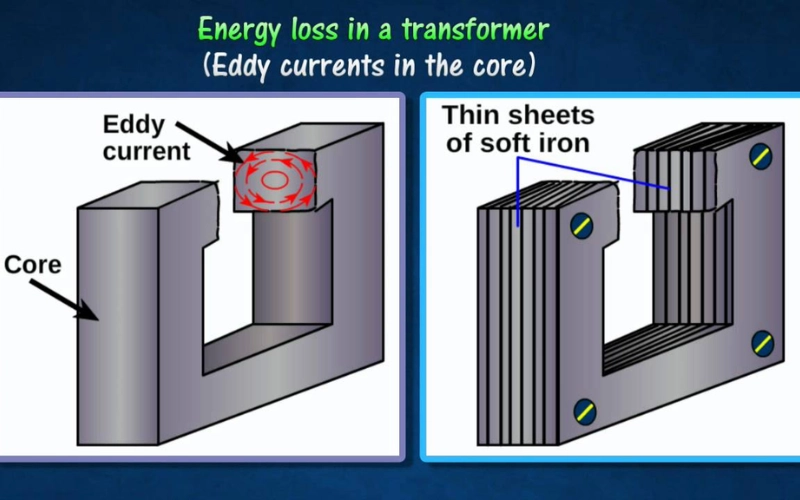
Eddy current losses, on the other hand, are caused by the flow of currents arising from the drift of magnetic flux around the core into the steel. These currents are created by the magnetic change that the body makes, a single loop of wire. Since the iron core could be a smart conductor, the eddy currents created by a cast iron core would be enormous.
Eddy currents do not contribute anything to the quality of the transformer. Instead, they counteract the flow of generated current by acting as a negative force, causing resistive heating and energy loss in the core.
Eddy current losses in the transformer core cannot be eliminated; however, they can be significantly reduced and controlled by reducing the thickness of the steel core. Instead of having a solid cast iron core due to the winding core material, the magnetic path is divided into several thin ferrous steel shapes called “laminations”.
Core lamination
The laminations used in the construction of the transformer are thin strips of insulated metal joined together to form a solid but laminated body, as we normally see from above. These laminations are protected from each other by a layer of enamel or paper to increase the actual strength of the core and thus increase the overall resistance to the movement of eddy currents.
The result of this isolation is that the troublesome power loss caused by eddy currents in the core is greatly reduced, so that the magnetic iron circuits of each transformer and various electromagnetic machines are all laminated. The use of laminations in a top transformer design minimizes eddy current losses.
Power losses caused by hysteresis and eddy currents in the magnetic path are commonly called “transformer core losses”. Since these losses occur in all magnetic materials due to changes in magnetic fields. Transformer core losses occur in a transformer whenever power is supplied to it, even if no load is connected to the coil. These hysteresis and eddy current losses are often called “transformer iron losses” because the resulting flux that causes these losses is constant regardless of the load.
Eddy current losses in a transformer are referred to as:
b t =K t F 2 K 2F b 2 m watts
Where,
K t = Eddy current constant
K F = shape constant
Insulating material for electrical machines
Insulating materials are essential components in electrical machines as they provide electrical insulation and protection against high voltages. They are available in a variety of forms, including thermosetting resins and thermoplastic polymers, selected depending on temperature, stress and mechanical strength requirements. These materials are often combined with fillers and additives to improve mechanical strength, thermal conductivity, flame resistance and moisture resistance. Special materials such as ceramics or composites are used in high voltage applications due to their superior dielectric strength. Insulating materials undergo rigorous testing to ensure compliance with industry standards. By selecting the appropriate insulating material, engineers ensure that electrical machines function reliably and safely under different operating conditions.
Copper losses
But there is also another type of energy loss associated with transformers, called “copper losses”. Copper losses in transformers arise mainly from the front and secondary windings of the transformer. Most transformer windings are made of copper wire with resistance in ohms (Ω). These resistances compete with the magnetizing currents that flow from one end to the other.
When a load is connected to the transformer coil, massive electrical currents flow in the first and secondary windings, and current, t and power (or the I 2 R) losses occur in the form of heat. Normally, losses in copper vary with the load current, being close to zero at no load and at their maximum at full load, when the current flow is highest.
The VA rating of a transformer is improved through better transformer design and construction to reduce these losses in the core and copper. Transformers with high voltage and current ratings require large diameter cross-section conductors to minimize their copper losses. A transformer's VA rating can be increased by increasing the rate of heat dissipation (better cooling) using compressed air or oil, or by improving the transformer's insulation so it can withstand higher temperatures.
Copper losses in a transformer are referred to as:
I2LR'2 + dispersion loss
Where,
EU M = transformer load
R'2 = Resistance on the secondary side of the transformer
Then we will also see that the transformer has:
There are no hysteresis losses caused by the hysteresis transformer.
Unlimited specific resistance of the core material, so that no eddy current losses occur.
The zero resistance of the winding shows zero I 2 R copper losses.
Araxá, em Minas Gerais, é agora o local da maior fábrica de nióbio do mundo especializada em baterias de carregamento ultrarrápido. A unidade tem capacidade para produzir 2.000 toneladas por ano do...
A soldagem é uma técnica essencial em diversas indústrias, desde a construção civil até a fabricação de automóveis. No entanto, um dos desafios mais comuns enfrentados pelos soldadores é a manutenç...
A solda com eletrodo revestido é uma técnica amplamente utilizada na indústria e construção civil devido à sua versatilidade e facilidade de aplicação. Neste artigo, vamos explorar detalhadamente o...
Ao escolher o material ideal para o telhado de sua casa, é importante considerar diversos fatores, como durabilidade, custo, desempenho térmico e estética. Neste artigo, vamos explorar as principai...
A construção civil está passando por uma transformação significativa, com a adoção de soluções inovadoras que visam aumentar a eficiência e a sustentabilidade dos processos. Uma dessas inovações é ...
Cálculo de Rigidez Longitudinal em Barras de Aço
A estabilidade e segurança em estruturas metálicas é um aspecto fundamental em projeto de construção. Como a rigidez de uma barra de aço é cruciais...
Cálculo de Esforço Torsional em Barras de Aço
O cálculo de esforço torsional em barras de aço é uma ferramenta essencial na análise de estruturas metalúrgicas, permitindo calcular o esforço aplica...
O Brasil, em 2023, lançou a Nova Indústria Brasil (NIB), uma política industrial ambiciosa voltada para a inovação e a sustentabilidade até 2033. Essa iniciativa tem tido um impacto significativo e...